
Glass-ceramic materials and electronic packages including same

a technology of glass-ceramic materials and electronic packages, applied in the direction of metal layered products, solid-state devices, electrical appliances, etc., can solve the problems of thermal expansion mismatch, glass and/or ceramic laminate material thermal expansion coefficient (hereinafter tec) not closely matching the support substrate or core on which the laminates are provided, and inability to withstand high temperature and high temperature, etc., to achieve low melting point, easy adjustment, and sufficient densification

Inactive Publication Date: 2005-12-01
KNOWLES CAZENOVIA
View PDF52 Cites 20 Cited by
  • Summary
  • Abstract
  • Description
  • Claims
  • Application Information

AI Technical Summary

Benefits of technology

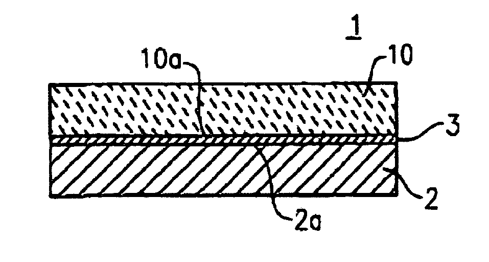
[0018] The glass-ceramic material according to the present invention has a thermal expansion coefficient that closely matches, or can be easily tailored to match, that of the desired support core or base material to which the multi-layer ceramic substrate is to be joined, is sufficiently densified when sintered to a relatively low temperature of about 900° C., has a low dielectric constant of 4-7.5, preferably less than 7, and also has a very low loss tangent (i.e., a high Q factor of greater than 400, more preferably, greater than 500, and even more preferably, greater than 550).
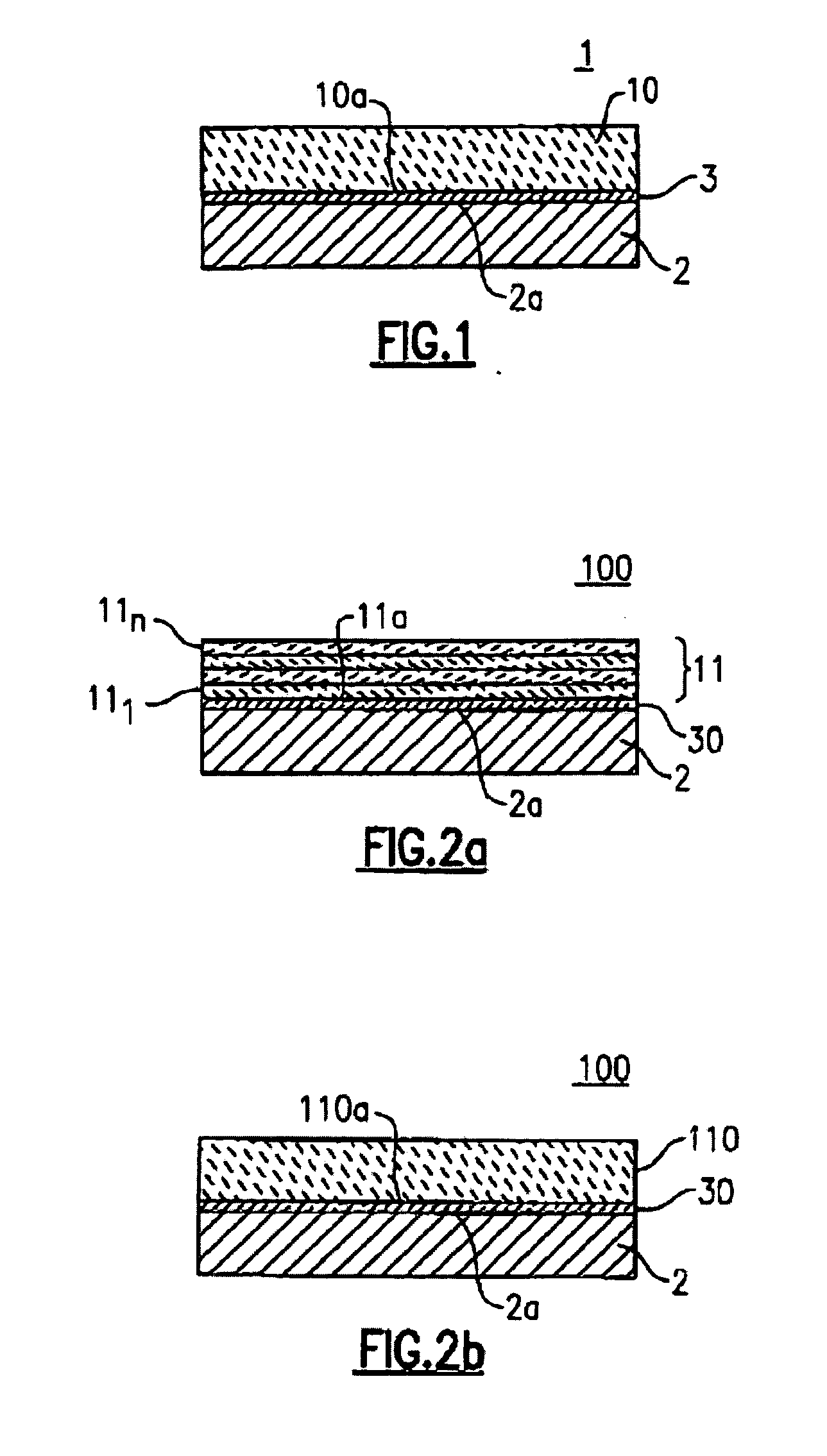
[0027] When the glass-ceramic of the present invention is provided in a powder or particulate form, the glass-ceramic can be easily processed. That is, the glass-ceramic according to the present invention can be easily processed into green multi-layer laminates by mixing the glass-ceramic powders with casting additives and tape casting the slurry into a green tape that can be made into a plurality of individual green sheets that are stacked (layered), laminated and heat-treated at a low temperature to remove organics and the like to form a green multi-layer structure.
[0028] The glass-ceramic according to the present invention can readily be used in a wide variety of high frequency electronic applications at frequencies up to about 60 gigahertz by virtue of the low dielectric constant and high Q factors. Since the glass-ceramic according to the present invention can be thermally processed and compositionally adjusted to have a wide TEC range while maintaining the desirable high frequency electrical characteristics of low dielectric constant (K) and high Q, it can be used in connection with a wide variety of members made from a variety of materials having a very high, or a very low, TEC in both co-firing and non-co-firing applications.
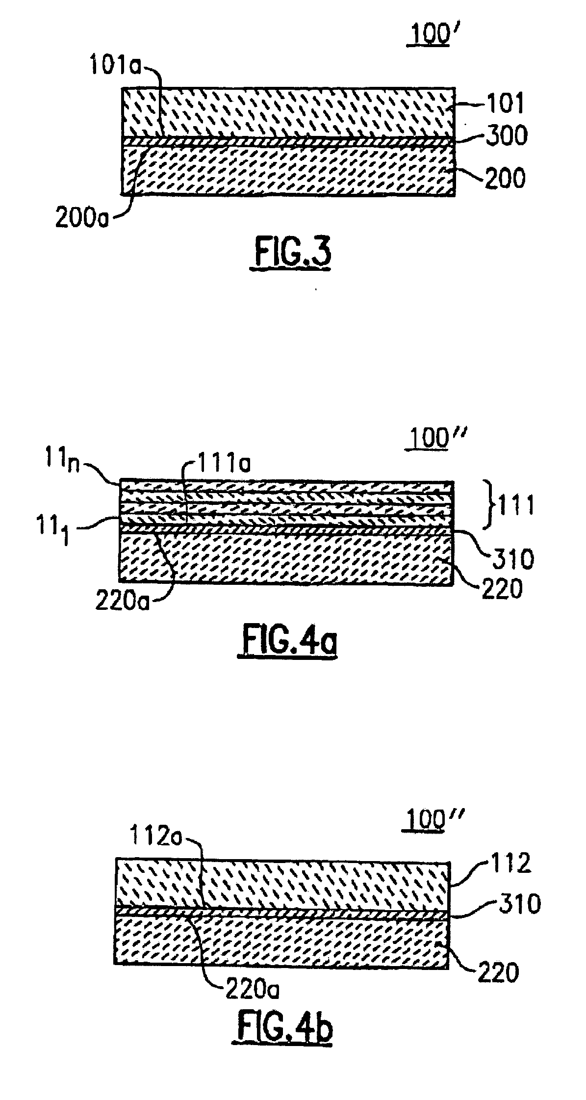
[0029] Examples of such members include sintered ceramic members made of AlN or Al2O3, and metal cores or metal supports made of KOVAR® or Cu / Mo / Cu, for use in heat sink applications, for example. The glass-ceramic according to the present invention can also be bonded with active components, such as integrated circuits, and silicon substrates and gallium arsenide members. In addition, the high TEC characteristics of the glass-ceramic according to one embodiment of the present invention (that can be obtained by compositional adjustment and heat treatment described in more detail below) enables this glass-ceramic to bond well with materials such as FR4 and other similar circuit board materials, or metals like Al or Cu, which have a high TEC of 16-22 ppm / ° C.
[0035] The TEC of the glass-ceramic according to the above embodiment of the present invention is easily adjusted to achieve a close TEC match with that of the support material (e.g., metal or sintered ceramic core) to which the glass-ceramic substrate is bonded in high frequency electronic applications. For example, since the αRT-300 of a non Ni-plated, laminated Cu / Mo / Cu metal core is about 5.3 ppm / ° C., and the αRT-300 of the glass-ceramic material according to one embodiment of the present invention is 5.4 ppm / ° C., the close match ensures good bonding (e.g., via a solder when the glass-ceramic material is metallized) without thermal mismatch defects such as cracking or bowing at low temperatures. When the TEC of the glass-ceramic material according to the present invention is significantly higher or lower than that of the material to which it is bonded, such as a Ni-plated, laminated or powder metallurgy Cu / Mo / Cu cores, the TEC of the glass-ceramic can be easily adjusted by adding a TEC adjusting additive, such as cordierite, fused silica, cristobalite, trydimite or quartz, to the glass-ceramic powder at the tape slurry preparation stage before forming the tapes that are laminated together to form the glass-ceramic substrate. Other TEC modifying agents can also be added as particulates at the tape slurry preparation stage so long as the added material has a crystal phase that has a desirably higher or lower TEC compared to the glass-ceramic, a low K and a high Q, in order to retain these preferred characteristics in the mixture.
[0038] The TEC of the glass-ceramic according to the above embodiment of the present invention is easily adjusted to achieve a close match with that of the support material on which is bonded in electronic applications. For example, according to one aspect of the present invention, the glass-ceramic further includes 0.1-20 wt % of a crystalline silica material such as quartz, cristobalite or trydimite or, alternatively, another material that crystallizes to produce these phases, that is added as a particulate to the glass-ceramic material during the tape slurry preparation stage. More preferably, 2-12 wt % of one of these is included. This is preferred when the TEC of the base material to which the glass-ceramic is to be bonded is higher than that of the glass-ceramic.

Problems solved by technology

The sintered glass and / or ceramic circuit boards are typically quite fragile, however, and in order to impart additional mechanical strength to the laminated board, the circuit boards are often attached to one or both sides of a suitable support substrate, or core material.
In most cases, however, the thermal expansion coefficient (hereinafter TEC) of the glass and / or ceramic laminate material does not closely match that of the support substrate or core on which the laminates are provided.
This thermal expansion mismatch problem is an important issue with low temperature co-fired ceramics (herein after LTCC) that are common in ceramic packaging applications, where a green laminated structure is sintered at a relatively low temperature after first being adhered to the metal support core.
The difference between the TEC of the material of the multi-layer substrate and that of the support substrate or core can, indeed, lead to substantial problems.
For example, significant stresses can develop, particularly at the bonding interface, that lead to warping or other mechanical damage, such as non-adherence to the support substrate and misalignment between vias that are provided in the multi-layered body and the corresponding electrical feed-throughs provided on the support substrate or core.
In severe cases, it is possible that the multi-layer substrate will even separate from the support, thus rendering the device unacceptable for use.
High melting point metals, however, have inferior electrical conductivity compared to Ag, Au, and Cu, for example.
Most ceramic and glass materials that have a suitable TEC do not also have a suitably low dielectric constant (K) and low loss tangent (or high Q factor), which makes these ceramic materials less desirable for high frequency electronic applications.
On the other hand, most ceramic and glass materials having a suitably low dielectric constant and high Q factor do not have a suitable TEC, and in particular, the TEC cannot be tailored to match that of the structure to which the multi-layer substrate is to be bonded.

Method used


Image

  • Glass-ceramic materials and electronic packages including same
  • Glass-ceramic materials and electronic packages including same
  • Glass-ceramic materials and electronic packages including same

Examples


example 1

[0083] A glass-ceramic having the composition shown in Table I was formed by batching and combining various oxides and carbonates (i.e., raw material forms) of each of the constituent components in the amounts shown. In Example 1, SrO was included in addition to the core composition. The raw material components were mixed (homogenized) and the mixture was placed in a Pt crucible, which was heated to a temperature of about 1500° C. for about 3 hours. The glass-ceramic was cooled and pulverized into a powder having an average particle size on the order of 8 μm.

example 2

[0084] A glass-ceramic powder having the composition shown in Table I was produced in the same manner as described above in connection with Example 1. In Example 2, BaO, instead of SrO, was included in addition to the core composition.

example 3

[0085] A glass-ceramic power having the composition shown in Table I was produced in the same manner described above in connection with Examples 1 and 2. In Example 3, ZnO, instead of BaO or SrO, was included in addition to the core composition.


PUM

PropertyMeasurementUnit
dielectric constantaaaaaaaaaa

Abstract

A glass-ceramic is provided having a thermal expansion coefficient in a range of 4.0 to 8.5 ppm / ° C., a dielectric constant in a range of 5-7 and a Quality factor Q of at least 400. The glass-ceramic consists essentially of SiO2 in a range of 40-55 wt %, Al2O3 in a range of 7-22 wt %, MgO in a range of 6 to less than 26 wt %, and at least one of BaO in an amount up to 35 wt %, SrO in an amount up to 37 wt % and ZnO in an amount up to 17 wt %. An electronic package is also provided, including one of a metal and sintered ceramic base member and a glass-ceramic substrate bonded to the base member.

Description

CROSS REFERENCE TO RELATED APPLICATIONS [0001] This application claims the benefit of U.S. Provisional Application Ser. No. 60 / 574,828 filed May 27, 2004 and U.S. Provisional Application Ser. No. 60 / 585,743 filed Jul. 6, 2004, the entireties of which are incorporated herein by reference. [0002] This application is related to copending U.S. patent application Ser. No. ______ (Attorney Docket No. 851—020 NP), filed contemporaneously herewith, entitled “LOW LOSS GLASS-CERAMIC MATERIAL, METHOD OF MAKING SAME AND ELECTRONIC PACKAGES INCLUDING SAME,” which claims the benefit of U.S. Provisional Application Ser. No. 60 / 585,689 filed Jul. 6, 2004, the entireties of which are incorporated herein by reference.FIELD OF THE INVENTION [0003] The present invention relates to glass-ceramic materials for use in high frequency (i.e., gigahertz range) electronic applications and various ceramic packaging assemblies including glass-ceramic materials for use in high frequency electronic applications. B...

Claims


Application Information

Patent Timeline
Patent Type & Authority Applications(United States)
IPC IPC(8): B32B15/00B32B15/04B32B17/06C03C10/00C03C12/00C04B35/18C04B35/195C04B37/02H01L23/15H05K1/03
CPCB32B15/04H05K1/0306B32B2311/12C03C10/0045C03C12/00C04B35/01C04B35/18C04B35/195C04B37/026C04B2235/3206C04B2235/3208C04B2235/3213C04B2235/3215C04B2235/3217C04B2235/3222C04B2235/3284C04B2235/3409C04B2235/3418C04B2235/3445C04B2235/3481C04B2235/447C04B2235/6025C04B2235/80C04B2235/9607C04B2237/125C04B2237/34C04B2237/341C04B2237/403C04B2237/405C04B2237/407C04B2237/408H01L23/15H01L2924/09701B32B17/06H01L2924/0002B32B17/061H01L2924/00B32B2305/80B32B2315/02B32B18/00B32B7/12
Inventor RITA, ROBERT A.
Owner KNOWLES CAZENOVIA
Learn More