Thermal management system and computer arrangement

a technology of thermal management system and computer arrangement, applied in the field of electrical cooling and computer arrangement, can solve the problems of high cost, inability to meet the requirements of electrical equipment, etc., and achieve the effect of low cost and high volum

Inactive Publication Date: 2006-01-19
FRUL VIKTOR
View PDF2 Cites 57 Cited by
  • Summary
  • Abstract
  • Description
  • Claims
  • Application Information

AI Technical Summary

Benefits of technology

[0028] It is the further object of the present invention to provide a method for ma...

Problems solved by technology

A major thermal management challenge is to adjust the constantly increasing heat emission from the electronic components to the constantly reducing weight and size of the computer arrangement.
Functional and designing division onto the heat removal and heat dissipating parts becomes typical for the modern computer architecture because the currently used cooling material and technologies can no longer manage the increased heat flux being coupled in one thermal management device.
Unfortunately, the currently used solutions are not free from the drawbacks.
The solid-state conductivity heat removal devices are heavy and their thermal conductivity often is beyond of what is required.
Another disadvantage of the commonly used aluminum and cooper heat spreaders is the CTE mismatch with CTEs of semiconductor materials by the factor 2-3.
The liquid cooling close-loop systems are heavy, roomy, and expensive in manufacturing.
Heat pipes are often bulky and fragile.
Thermoelectric cooling devices are heavy and bulky; their energy consumption is in a range that puts them outside of battery-driven applications.
Distribution of air streams within the finned structure is uneven due to turbulent nature of air flow and formation of the flow stagnation areas.
Conventional heat sink-fan tandems produce a large amount of high velocity air flow that is the main source of computer noise.
A large amount of air pumped through the computer causes deposition of contaminations on the surface of electronic components that reduces heat exchange additionally.
Use of air filtration devices for fan air movers is limited because of the air pressure developed by air fans do not meet the pressure drop conditions in the air filtration systems.
A large volume air flows produced by fans are used in inefficient way in computer systems.
Unfortunately, the prior art does not disclose solutions able to meet these requirements.
Still another disadvantage of the common design heat sinks is that they occupy too much phys...

Method used


Image

  • Thermal management system and computer arrangement
  • Thermal management system and computer arrangement
  • Thermal management system and computer arrangement

Examples


Embodiment Construction

[0064] A description of preferred embodiments of the invention follows.

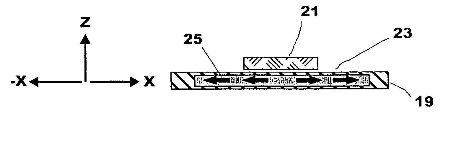
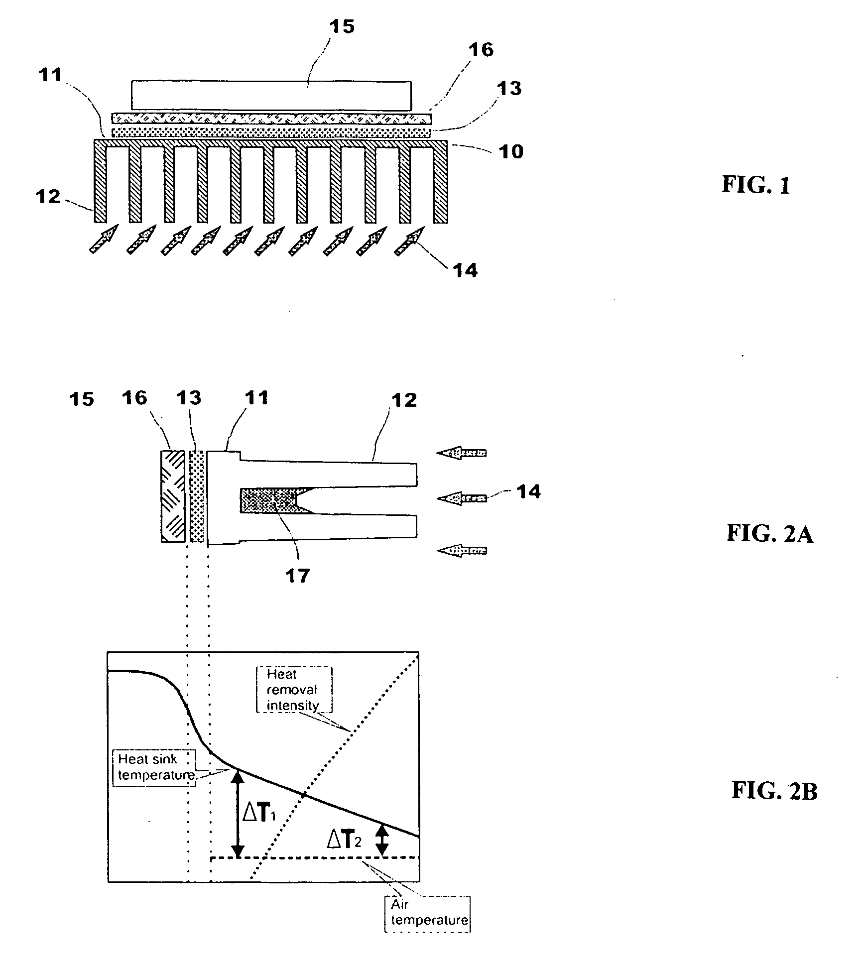
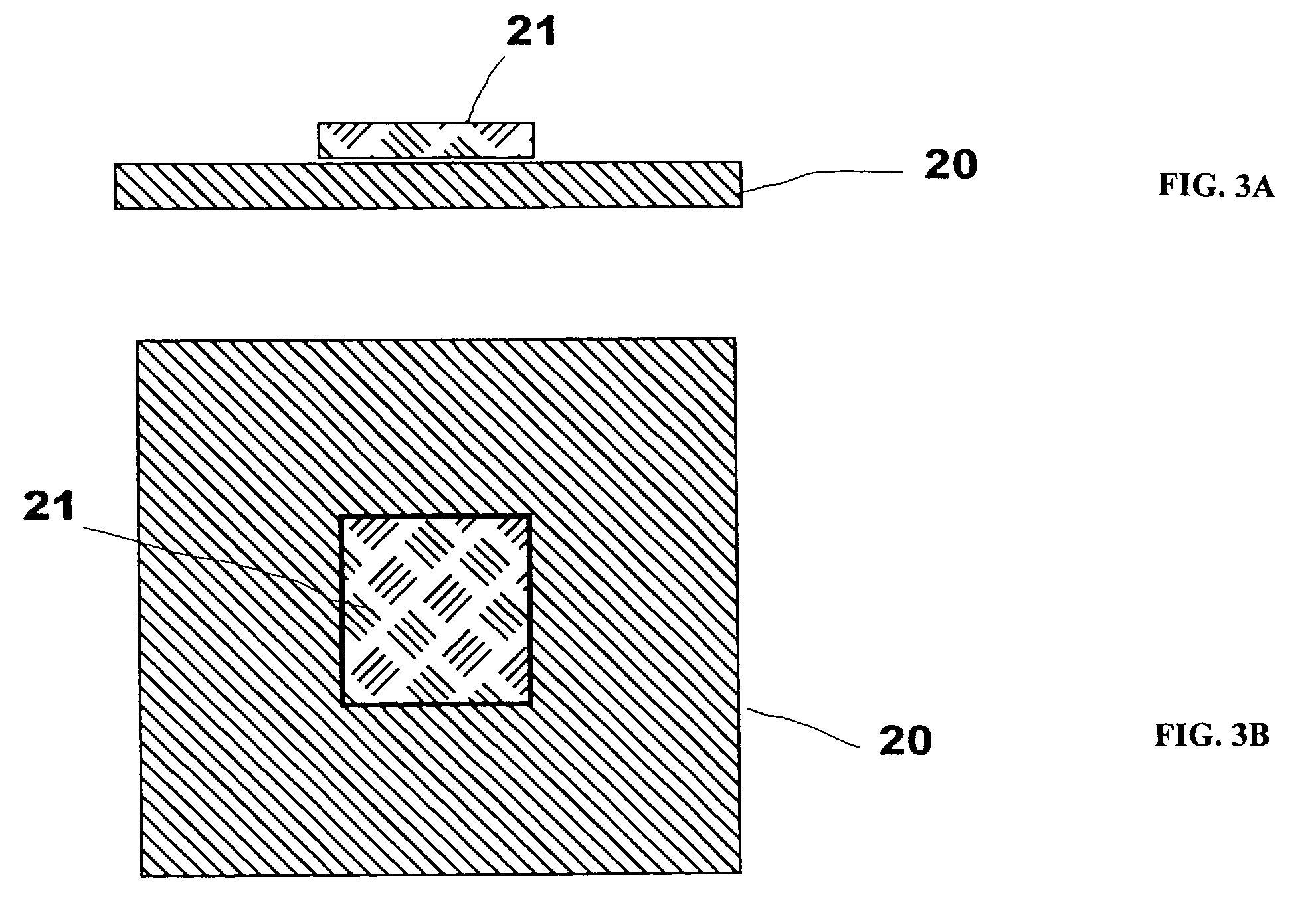
[0065] Illustrative embodiments of the thermal management system for electronics and computer arrangement according to the present invention are shown in FIGS. 3-15. As will be readily apparent to those skilled in the upon a complete reading of the present application, the present cooling device and electronic system arrangement are applicable to a variety of computer systems (such as servers, personal computers, notebooks, and the like) other than the embodiment illustrated herein, and moreover to electronic and electrical devices other than computer systems, including, but not limited to, power supply, plasma TV, automotive electronics, airborne electronics, and the like. Several non-limiting embodiments are provided and described in more detail herein. Embodiments include, but are not limited to, (a) high conductivity micro composite heat sinks, (b) graphite fiber brush-type heat sinks, (c) CTE controlled sub...


PUM

PropertyMeasurementUnit
Porosityaaaaaaaaaa
Weightaaaaaaaaaa
Electrical conductivityaaaaaaaaaa

Abstract

It is the object of the present invention to provide a low weight, compact, low vertical profile thermal management system for removing heat from electronic components. The thermal management system comprises of a plurality of “flow-through” type cooling devices, a source of filtered pressurized fluid suitable for use as a coolant, and a fluid delivering device that supplies the cooling devices with fluid. A preferred fluid is air, such as a filtered pressurized air. The cooling device is comprised of a high conductivity metal matrix composite heat spreader, a miniature heat sink, preferably of the same material, a permeable heat exchanger with high specific surface, and a closure that provides structural integrity of the cooling device.

Description

RELATED APPLICATIONS [0001] This application claims the benefit of U.S. Provisional Application No. 60 / 591,254, filed on Jul. 26, 2004 and U.S. Provisional Application No. 60 / 560,382, filed on Apr. 7, 2004. The entire teachings of the above applications are incorporated herein by reference.FIELD OF INVENTION [0002] The present invention relates to a thermal management system, especially electronics cooling and computer arrangement, and more particularly, to high performance electronics thermal management device that achieves high heat dissipation rates and provides a compact arrangement in which the electronic components are disposed with maximized space and weight efficiency. BACKGROUND OF THE INVENTION [0003] High power electronic components continue to have an increasing demand for higher power dissipating waste heat generated during computer operating within a relatively confined space. A major thermal management challenge is to adjust the constantly increasing heat emission fro...

Claims


Application Information

Patent Timeline
IPC IPC(8): F28F7/00B22F9/00C22C5/00A61K33/42F28F3/12F28F13/00H01L23/373H01L23/467
CPCB22F2998/00C22C2204/00F28F3/12F28F13/003F28F21/02H01L2224/32225H01L23/467H01L2924/3011H01L23/3733B22F7/006
Inventor FRUL, VIKTOR
Owner FRUL VIKTOR
Why Eureka
Try Eureka