Coated zeolite catalysts and use for hydrocarbon conversion

a technology of zeolite and catalyst, which is applied in the field of coating zeolite catalyst and hydrocarbon conversion, can solve the problems of adverse effects of reactants entering the pores of zeolite, zeolite crystals, and non-selective reactions on the external surface acid sites of zeolites, and achieve the effect of improving performan

Inactive Publication Date: 2006-01-19
EXXONMOBIL CHEM PAT INC
View PDF7 Cites 34 Cited by
  • Summary
  • Abstract
  • Description
  • Claims
  • Application Information

AI Technical Summary

Benefits of technology

[0011] The coated zeolite catalysts of the present invention have enhanced performance when utilized in hydrocarbon conversion processes. The coated zeolite catalysts of the present invention finds particular application in hydrocarbon conversion processes where catalyst acidity in combination with zeolite structure are important for reaction selectivity. Examples of such processes include catalytic cracking, alkylation, dealkylation, dehydrogenation, disproportionation, and transalkylation reactions. The coated zeolite catalysts of the present invention also find application in other hydrocarbon conversion processes in which carbon containing compounds are changed to different carbon containing compounds. Examples of such processes include hydrocracking, isomerization, dewaxing, oligomerization, and reforming processes.

Problems solved by technology

Non-selective reactions on the external surface acid sites of zeolites are usually not desirable because they are not subject to the shape selective constraints imposed on those reactions occurring within the channels of the zeolites and are often not desirable.
For example, the surface acid sites can adversely effect reactants entering the pores of the zeolite and products exiting the pores of the zeolite.
A problem associated with these procedures is that they can degrade the zeolite crystals and / or cause the zeolite crystals to lose sorption capacity.
Still further, dealumination can also reduce the overall activity of the zeolite, which can result in reduced catalyst activity and / or activity maintenance.

Method used


Image

  • Coated zeolite catalysts and use for hydrocarbon conversion
  • Coated zeolite catalysts and use for hydrocarbon conversion
  • Coated zeolite catalysts and use for hydrocarbon conversion

Examples


example 1

I. Catalyst A

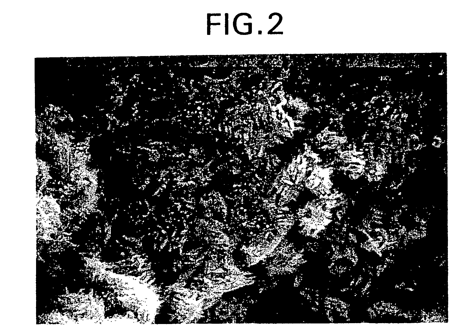
[0096] Catalyst A comprised 70 wt. % ZSM-5 core crystals (average particle size of 3.0 microns) having a silica to alumina mole ratio of about 66:1 and 30 wt. % silicalite coating crystals. The catalyst was prepared by first mixing the ZSM-5 core crystals with amorphous silica and then extruding the mixture into a silica bound extrudate. Next, the silica binder of the extrudate was converted to the second zeolite by aging the aggregate at elevated temperatures in an aqueous solution containing a template and hydroxy ions sufficient to covert the silica to the binder crystals. The resulting product was then washed, dried, calcined, ion exchanged into the hydrogen form, and crushed. FIG. 1 is a SEM micrograph of Catalyst A.

II. Catalyst B

[0097] Catalyst B comprised about 70 wt. % MFI structure type zeolite core crystals (average particle size of 3.0 microns) having a silica to gallia mole ratio of about 100:1, 30 wt. % MFI structure type binder crystals having a silic...

example 2

[0112] Preparation of platinum-containing zeolite coated MFI type gallium silicate catalyst.

[0113] MFI type gallosilicate crystals (4 micron size spherical crystals and SiO2 / Ga2O3=48) were formed into silica bound extrudates or follows:

Components UsedFor PreparationQuantity (Grams)Component No.Silica Sol (Nalcoag 1034)49.441Silica gel (Aerosil 300)4.722H2PtCl6.6H2O0.933Water11.07Rinse Water3.274Gallium silicate MFI Crystals49.865Extrusion aid (hydroxypropyl0.346methyl cellulose

[0114] The components were mixed in a dough mixer in the order Indicated. After adding the extrusion aid, and mixing for about 15 minutes, a dough was obtained. The dough was divided into several portions and dried in an oven at 120° C. for 16 hours. The dried portions were crushed, and then calcined at 490° C. for 24 hours in air.

[0115] The silica coated core crystals were converted into zeolite bound zeolite as follows:

Components UsedFor PreparationQuantity (Grams)Component ANaOH pellets (98.7%)1.162Wa...

example 3

[0124] A coated zeolite catalyst was prepared which comprised about 70 wt. % ZSM-5 core crystals (average particle size of 3.0 microns) having a silica to alumina mole ratio of about 70:1 and 30 wt. % silicalite coating crystal. The catalyst was prepared by first mixing the ZSM-5 core crystals with amorphous silica and then extruding the mixture into a silica bound extrudate. Next, the silica binder of the extrudate was converted to the second zeolite by aging the aggregate at elevated temperatures in an aqueous solution containing a template and hydroxy ions sufficient to covert the silica to the binder crystals. The resulting product was then washed, dried, calcined, ion exchanged into the hydrogen form, and crushed. An additional coating of silicalite was applied to the zeolite coated product by first mixing the coated ZSM-5 core crystals with amorphous silica and then extruding the mixture into a silica bound extrudate. Next, the silica binder of the extrudate was converted to c...


PUM

PropertyMeasurementUnit
particle sizeaaaaaaaaaa

Abstract

There is provided a coated zeolite catalyst in which the accessibility of the acid sites on the external surfaces of the zeolite is controlled and a process for converting hydrocarbons utilizing the coated zeolite catalyst. The zeolite catalyst comprises core crystals of a first zeolite and a discontinuous layer of smaller size second crystals of a second zeolite which cover at least a portion of the external surface of the first crystals The coated zeolite catalyst finds particular application in hydrocarbon conversion processes where catalyst activity in combination with zeolite structure are important for reaction selectivity, e.g., catalytic cracking, alkylation, disproportional of toluene, isomerization, and transalkylation reactions.

Description

[0001] This application claims priority to U.S. Provisional Patent Application No. 60 / 067,415, filed Dec. 3, 1997. FIELD OF THE INVENTION [0002] This invention relates to coated zeolite catalysts having controlled external surface acidity and the use of the coated zeolite catalysts in hydrocarbon conversion processes. BACKGROUND OF THE INVENTION [0003] Crystalline microporous molecular sieves, both natural and synthetic, have been demonstrated to have catalytic properties for various types of hydrocarbon conversion processes. In addition, the crystalline microporous molecular sieves have been used as adsorbents and catalyst carriers for various types of hydrocarbon conversion processes, and other applications. These molecular sieves are ordered, porous, crystalline material having a definite crystalline structure as determined by x-ray diffraction, within which there are a large number of smaller cavities which may be interconnected by a number of still smaller channels or pores. Th...

Claims


Application Information

Patent Timeline
Patent Type & Authority Applications(United States)
IPC IPC(8): B01J29/06C10G11/04C07C15/12C07C5/22B01J29/40B01J29/70B01J29/80B01J35/02C10G3/00C10G11/05C10G35/06C10G35/095C10G45/64
CPCB01J29/40C10G2400/20B01J29/80B01J35/023B01J37/0246B01J2229/12B01J2229/26B01J2229/42B01J2229/62C07C2/864C07C5/2708C07C6/123C07C2529/40C07C2529/70C07C2529/87C10G11/05C10G35/065C10G35/095C10G45/64B01J29/70C10G2300/708C10G2300/1044C10G3/49C10G2300/4018C10G3/45C10G3/47C07C15/08Y02P30/20Y02P20/52
Inventor VAN DEN BERGE, JANNETJE MAATJEMOHR, GARY DAVIDCLEM, KENNETH RAYMORTIER, WILFRIED JOZEFMERTENS, MACHTELD MARIABRADFORD, MICHAEL C.
Owner EXXONMOBIL CHEM PAT INC
Why Eureka
Try Eureka