High temperature, minimally invasive optical sensing modules

a technology of optical sensing modules and high temperature, applied in the field of optical sensors, can solve the problems of sensor malfunction, erroneous data, and low cost of low loss optics, and achieve the effects of low cost, low loss, and minimal invasiveness

Inactive Publication Date: 2006-01-26
UNIV OF CENT FLORIDA +1
View PDF3 Cites 16 Cited by
  • Summary
  • Abstract
  • Description
  • Claims
  • Application Information

AI Technical Summary

Benefits of technology

[0006] The present invention provides a robust optical sensor that can be remoted, is minimally invasive, works at high temperatures (e.g., 2000 C) and pressures, requires low cost low loss optics, has high sensing resolution over any extended unambiguous range, and provides easy access to many sensing points.

Problems solved by technology

Any deformity will cause not only the Fabry-Perot etalon calibration and behavior to change but also cause misalignment with the receive fiber-optics as used in prior art fiber-optic sensors based on SiC thin films.
In effect, such a sensor will malfunction and provide erroneous data.

Method used


Image

  • High temperature, minimally invasive optical sensing modules
  • High temperature, minimally invasive optical sensing modules
  • High temperature, minimally invasive optical sensing modules

Examples


Embodiment Construction

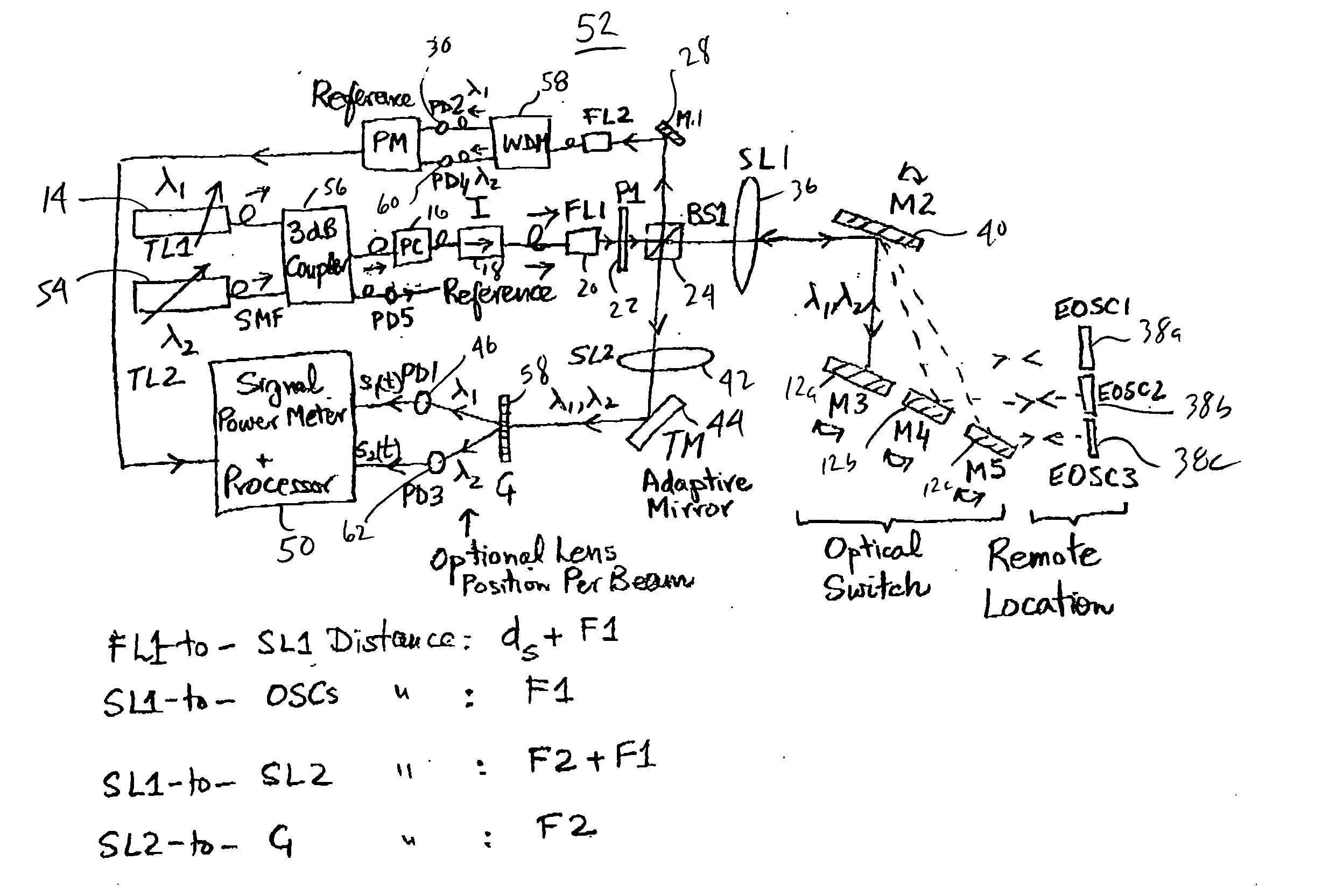
[0024]FIG. 1 shows an embodiment of a high temperature minimally invasive optical sensor 10 using freespace interface optics. The sample frontend is composed for example of three Etalon Optical Sensor Chips (EOSCs) 12a, 12b, 12c using, for example, single crystal Silicon Carbide (SiC). Light from a tunable laser 14 passes via fiber-optics such as a polarization controller (PC) 16 and isolator (I) 18 to exit via a fiber lens (FL1) 20 to produce a freespace beam 22 with its minimum Gaussian beam waist radius wi located at a distance ds from FL1, this distance also called the half-self imaging distance (see Martin van Buren and N. A. Riza, “Foundations for low loss fiber gradient-index lens pair coupling with the self-imaging mechanism,” Applied Optics, LP, Vo.42, No.3, Jan. 20, 2003). This light then passes via a beam splitter BS124 to produce a reflected beam 26 that via mirror M128 enters a freespace coupled photodetector PD230 to produce a level electrical signal 32 indicating the ...


PUM


Abstract

A remote temperature sensing system includes a light source selectively producing light at two different wavelengths and a sensor device having an optical path length that varies as a function of temperature. The sensor receives light emitted by the light source and redirects the light along the optical path length. The system also includes a detector receiving redirected light from the sensor device and generating respective signals indicative of respective intensities of received redirected light corresponding to respective wavelengths of light emitted by the light source. The system also includes a processor processing the signals generated by the detector to calculate a temperature of the device.

Description

SPECIFIC DATA RELATED TO INVENTION [0001] This application claims the benefit of U.S. provisional application No. 60 / 590,672 filed on Jul. 23, 2004 and U.S. provisional application No. 60 / 633,900 filed on Dec. 7, 2004.BACKGROUND OF THE INVENTION [0002] The present invention relates to optical sensors and, more particularly, to optical sensors using optical interferometry to implement remote sensing. [0003] There are numerous vital sensing scenarios in commercial and defense sectors where the environment is extremely hazardous. Specifically, the hazards can be for instance due to extreme temperatures, extreme pressures, highly corrosive chemical content (liquids, gases, particulates), nuclear radiation, biological agents, and high Gravitational (G) forces. Realizing a sensor for such hazardous environments remains to be a tremendous engineering challenge. One specific application is fossil fuel fired power plants where temperatures in combustors and turbines typically have temperatur...

Claims


Application Information

Patent Timeline
Patent Type & Authority Applications(United States)
IPC IPC(8): G01B9/02
CPCG01J5/38G01K5/52G01J5/60
Inventor RIZA, NABEEL AGHAPEREZ, FRANK
Owner UNIV OF CENT FLORIDA
Why Eureka
Try Eureka