Power module and electric transportation apparatus incorporating the same

a technology of power modules and electric transportation devices, which is applied in electrical devices, semiconductor devices, semiconductor/solid-state device details, etc., can solve the problems of increasing the length of wires, increasing the temperature of the fets and diodes used in such a power module, and heating problems associated with the resistance of wires, so as to achieve the effect of large curren

Inactive Publication Date: 2006-02-02
YAMAHA MOTOR CO LTD
View PDF5 Cites 4 Cited by
  • Summary
  • Abstract
  • Description
  • Claims
  • Application Information

AI Technical Summary

Benefits of technology

[0015] In order to overcome the problems of conventional power modules described above, preferred embodiments of the present invention provide a power module which does not induce much heating, and which is thus reliable or capable of allowing a large current to be flowed therethrough.
[0038] In accordance with the power module according various preferred embodiments of the present invention, electrical connections to semiconductor devices are realized preferably by metal plates. Therefore, as compared to a conventional power module in which wires are used, the semiconductor devices can be electrically connected with a low resistance, and heat loss at the electrical connection elements can be reduced. Moreover, in accordance with the power module of the present invention, the semiconductor devices are stacked so as not to overlie one another. This prevents concentration of the heat generated in the semiconductor devices due to overlapping of elements, and permits uniform radiation of the heat within the overall power module. Thus, malfunctioning and / or deterioration of the semiconductor devices due to local concentration of heat are minimized, whereby the reliability of the overall power module is enhanced.

Problems solved by technology

FETs and diodes which are used in such a power module are likely to increase in temperature due to a large current flowing therethrough.
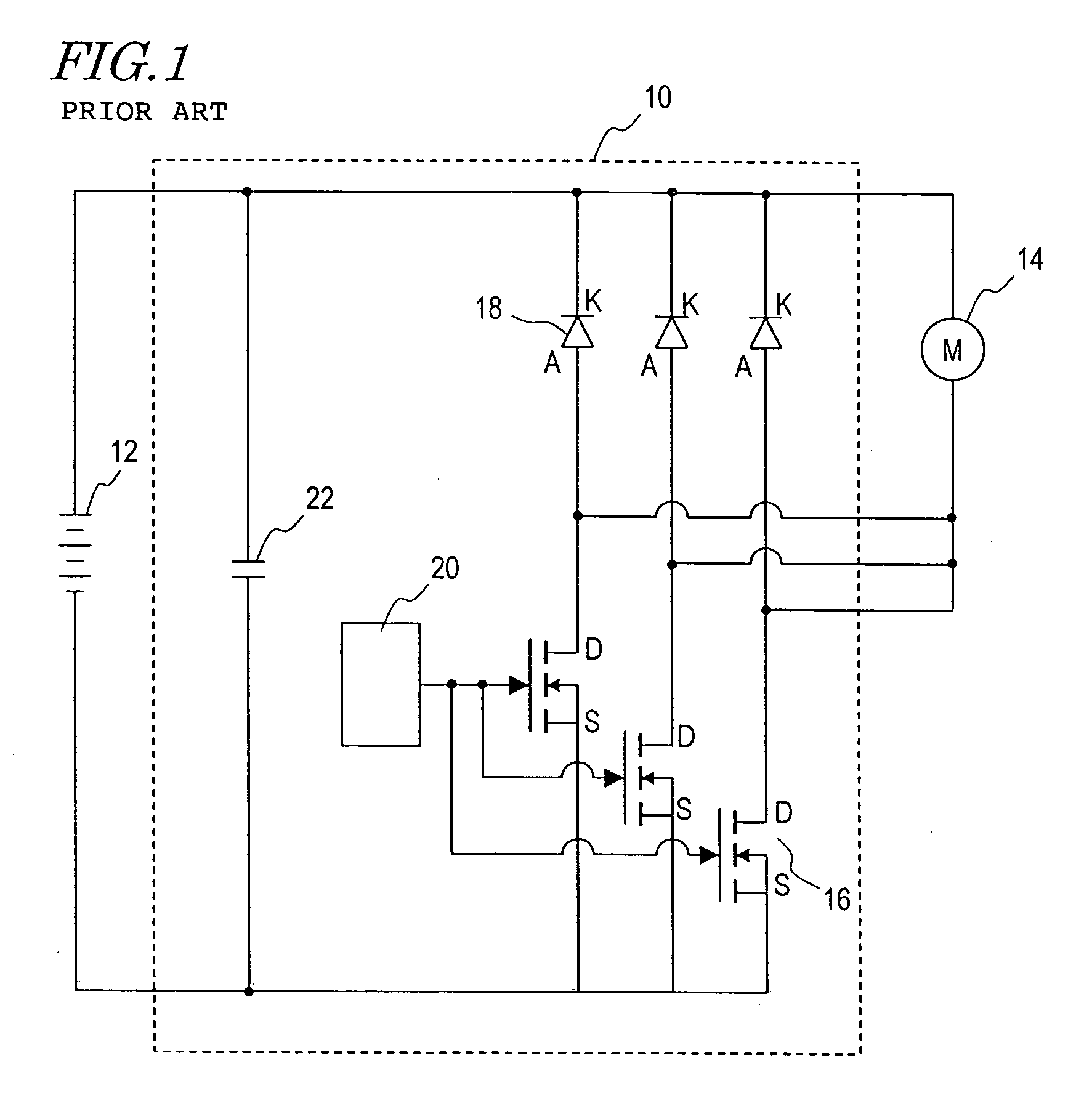
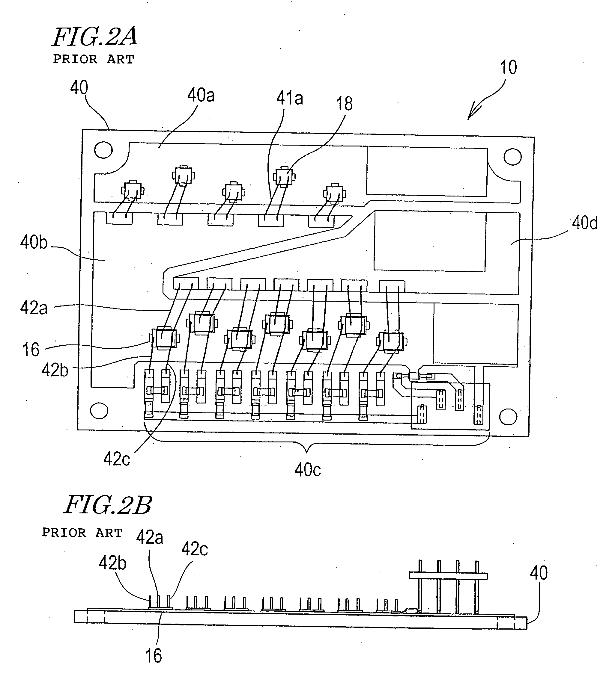
However, doing so will require an increase in the length of the wires 42a connected to the FETs 16, which in turn will cause heating problems associated with the wire resistance.
However, the number of wires that can be connected to an FET 16 is limited by the size of each electrode of the FET 16, and thus it is impossible to connect too many wires to the FET 16.
Any increase in the number of wires or the wire thickness will result in an increased bonding area, and consequently, the ultrasonic waves may damage the FETs, possibly reducing the reliability of the FETs.
Since an insulating layer generally has a poor thermal conductivity, the addition of the insulating layer will result in a reduced heat-releasing ability of the printed wiring board, thus lowering the efficiency with which the heat generated in the FETs and wires is dissipated to the exterior via the printed wiring board.
In this case, however, the thickness of the conductive layer may make it difficult to perform patterning by etching or the like.
Moreover, although Japanese Laid-Open Patent Publication No. 2004-47850 discloses using a thin film circuit pattern to realize such electrical connections, a thin film circuit pattern cannot be considered as having a sufficiently low resistance as compared to that of a conventional wire.
Therefore, there is a possibility that the problems associated with heating may not be solved.

Method used


Image

  • Power module and electric transportation apparatus incorporating the same
  • Power module and electric transportation apparatus incorporating the same
  • Power module and electric transportation apparatus incorporating the same

Examples


Embodiment Construction

[0058] Hereinafter, preferred embodiments of the present invention will be described with reference to the accompanying drawings. FIG. 3 is a circuit diagram schematically showing a driving system of a transportation apparatus incorporating a power module according to a preferred embodiment the present invention. The power module according to various preferred embodiments of the present invention can be used in a variety of transportation apparatuses which utilize a motor as a driving mechanism. In the present specification, a “power module” is defined as any device which supplies a large current (10 A or more) to a motor or the like while controlling the current by using a semiconductor device.

[0059] As shown in FIG. 3, the transportation apparatus preferably includes a power module 101, a motor 102, a battery 103, a smoothing capacitor 104, and a control circuit 105. In the present preferred embodiment, the motor 102 is preferably a brush-less DC motor. To the three terminals of ...


PUM


Abstract

A power module includes a plurality of first semiconductor devices disposed so as to define a first layer in a substantially common plane, a plurality of second semiconductor devices disposed so as to define a second layer in a substantially same plane, and at least one metal plate electrically connected to at least two semiconductor devices selected from among the plurality of first and second semiconductor devices. The first layer and second layer are stacked such that the plurality of second semiconductor devices do not overlap the plurality of first semiconductor devices.

Description

BACKGROUND OF THE INVENTION [0001] 1. Field of the Invention [0002] The present invention relates to a power module and an electric transportation apparatus including the same. More particularly, the present invention relates to a power module for supplying power to a motor which is used as a driving mechanism of a transportation apparatus, and an electric transportation apparatus including such a power module. [0003] 2. Description of the Related Art [0004] In recent years, transportation apparatuses which utilize an electric motor (hereinafter simply referred to as a “motor”) as a driving mechanism have been drawing attention, due to concerns about environmental or energy issues, etc. As compared to an internal combustion engine, a motor is advantageous in that it produces little operating noise while being operated, and permits a great amount of design freedom in its outer shape, thus enabling the motor to be installed close to a driving mechanism. Therefore, with a motor, it is ...

Claims


Application Information

Patent Timeline
Patent Type & Authority Applications(United States)
IPC IPC(8): H01L29/76
CPCH01L25/071H02M7/003H01L2924/0002H01L2924/00
Inventor MURAI, TAKAYUKIMORITA, KOJI
Owner YAMAHA MOTOR CO LTD
Why Eureka
Try Eureka