Implant device

a technology of implants and devices, applied in the field of implants, can solve the problems of most costly health problems in society, pain and pathology of the spine, and large suffering of victims, and achieve the effects of facilitating the positioning of implants, facilitating insertion, and minimal chance of surgical difficulty

Inactive Publication Date: 2006-02-16
SPINECO
View PDF58 Cites 131 Cited by
  • Summary
  • Abstract
  • Description
  • Claims
  • Application Information

AI Technical Summary

Benefits of technology

[0023] In yet another and / or alternative non-limiting aspect of the present invention, the implant can be formed of a substantially inert or biologically compatible material for use in humans. The implant can be designed to be used with another implant that is designed to be placed in the intervertebral disc space that was formerly occupied by at least a portion of an intervertebral disc; however, it can be appreciated that the implant can be used with other or additional implants. The implant can be designed to be readily inserted by established surgical procedures, with minimal chances of surgical difficulty; however, this is not required. The implant can be at least partially formed of materials such as, but not limited to, bone, stainless steel, titanium, chromemolybdenum, cobalt chromium alloy, chrome or chrome alloys, cobalt or cobalt alloys, polycarbonate, polypropylene, polyethylene, polymethylmethacrylate, polysolfone types filled with glass and / or carbon fibers, and various types of carbon and fiber reinforced polymers. The material can be wear resistant; however, this is not required. The implant can include one or more openings and / or structures in the head and / or lower portion to facilitate in the positioning of the implant relative to the bone or cartilage and / or to secure the implant in the patient. One or more of the openings and / or structures in the implant can be adapted to receive an instrument for guiding, inserting, and / or removing the implant in the patient. Further details of the implant are set forth in United States Patent Publication No. 2004 / 0243130, which is incorporated herein.
[0024] In a further and / or alternative non-limiting aspect of the present invention, the implant can be designed to be at least partially connected to the bone and / or cartilage after an opening in the bone and / or cartilage has been formed; however, this is not required. When an opening or hole is formed, such opening or hole can be formed by a drill or similar device; however, this is not required. The size of the opening or hole can be selected to be larger, smaller or the same size as the cross-sectional area of the implant. The opening or hole can be inserted in the bone and / or cartilage to reduce damage to the bone and / or cartilage when the implant is subsequently inserted in the bone and / or cartilage, and / or to provide a guide opening for insertion of the implant; however, this is not required.
[0025] In a still further and / or alternative non-limiting aspect of the present invention, a sleeve can be used in conjunction with one or more implants. When an opening or hole is formed in the bone and / or cartilage, the sleeve can be designed to be at least partially inserted into the opening or hole prior to or during the insertion of the implant in the bone and / or cartilage; however, this is not required. As can be appreciated, the sleeve can designed to be partially or fully inserted into the bone and / or cartilage with a hole or opening being first inserted into the bone and / or cartilage. The sleeve can be designed to be a temporary or permanent device. When the sleeve is a temporary device, the sleeve can be designed to be at least partially inserted in the bone and / or cartilage and then removed prior to the insertion of the implant into the bone and / or cartilage; however, this is not required. When the sleeve is inserted into a preformed hole or opening in the bone and / or cartilage, and / or the sleeve is used to at least partially form a hole or opening in the bone and / or cartilage, the sleeve can be used to a) inhibit or prevent contamination of the formed opening or hole in the bone and / or cartilage, b) inhibit or prevent growth of tissue and / or bone in the formed opening or hole, c) allow time for the bone and / or tissue around the opening or hole to at least partially heal (e.g., 1-20 weeks), d) facilitate in connecting or securing the implant to the bone and / or cartilage, e) enable one or more implants that are at least partially connected to the sleeve to be unsecured and / or disconnected from the sleeve with minimal, if any, damage to the surrounding bone and / or cartilage (i.e., minimally-invasive), and / or f) enable one or more implants that are at least partially secured to the sleeve to be replaced with one or more other implants with minimal, if any, damage to the surrounding bone and / or cartilage (i.e., minimally-invasive). As can be appreciated, there can be other uses for this temporary or removable sleeve. The sleeve can also be a permanent or non-removable device that is designed to be maintained in the opening or hole formed in the bone and / or cartilage. In such a use, the sleeve can be used to a) inhibit or prevent contamination of the formed opening or hole in the bone and / or cartilage, b) inhibit or prevent growth of tissue and / or bone in the formed opening or hole, c) allow time for the bone and / or tissue around the opening or hole to at least partially heal (e.g., 1-20 weeks), d) facilitate in connecting or securing the implant to the bone and / or cartilage, e) enable one or more implants that are at least partially connected to the sleeve to be unsecured and / or disconnected from the sleeve with minimal, if any, damage to the surrounding bone and / or cartilage (i.e., minimally-invasive), and / or f) enable one or more implants that are at least partially secured to the sleeve to be replaced with one or more other implants with minimal, if any, damage to the surrounding bone and / or cartilage (i.e., minimally-invasive). As can be appreciated, other uses can be used for this permanent or non-removable sleeve. The sleeve can be inserted by a variety of techniques such as, but not limited to, percutaneous insertion, computerized image guidance, stereo-static imaging, robotic surgery, etc.

Problems solved by technology

One of the most costly health problems in society involves back pain and pathology of the spine.
These problems can affect individuals of all ages and can result in great suffering to victims.
Such changes can cause painful excessive motion, or collapse of a motion segment resulting in the contraction of the spinal canal and compression of the neural structures, causing debilitating pain, paralysis or both, which in turn can result in nerve root compression or spinal stenosis.
Although this procedure may result in some minor loss and flexibility in the spine due to the relatively large number of vertebrae, the minor loss of mobility is typically acceptable.
Any infection that occurs around the pedicle screw can slow the healing process and / or damage the bone around the pedicle screw thereby weakening the connection between the bone and pedicle screw.

Method used


Image

  • Implant device
  • Implant device
  • Implant device

Examples


Embodiment Construction

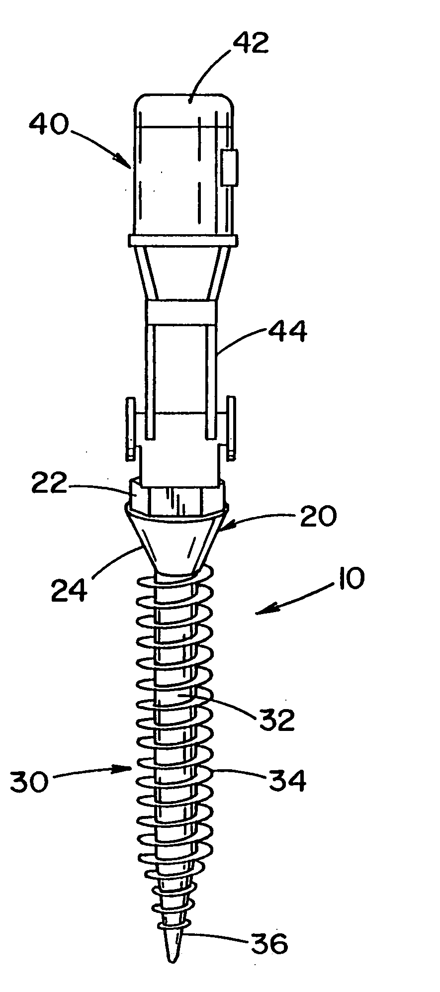
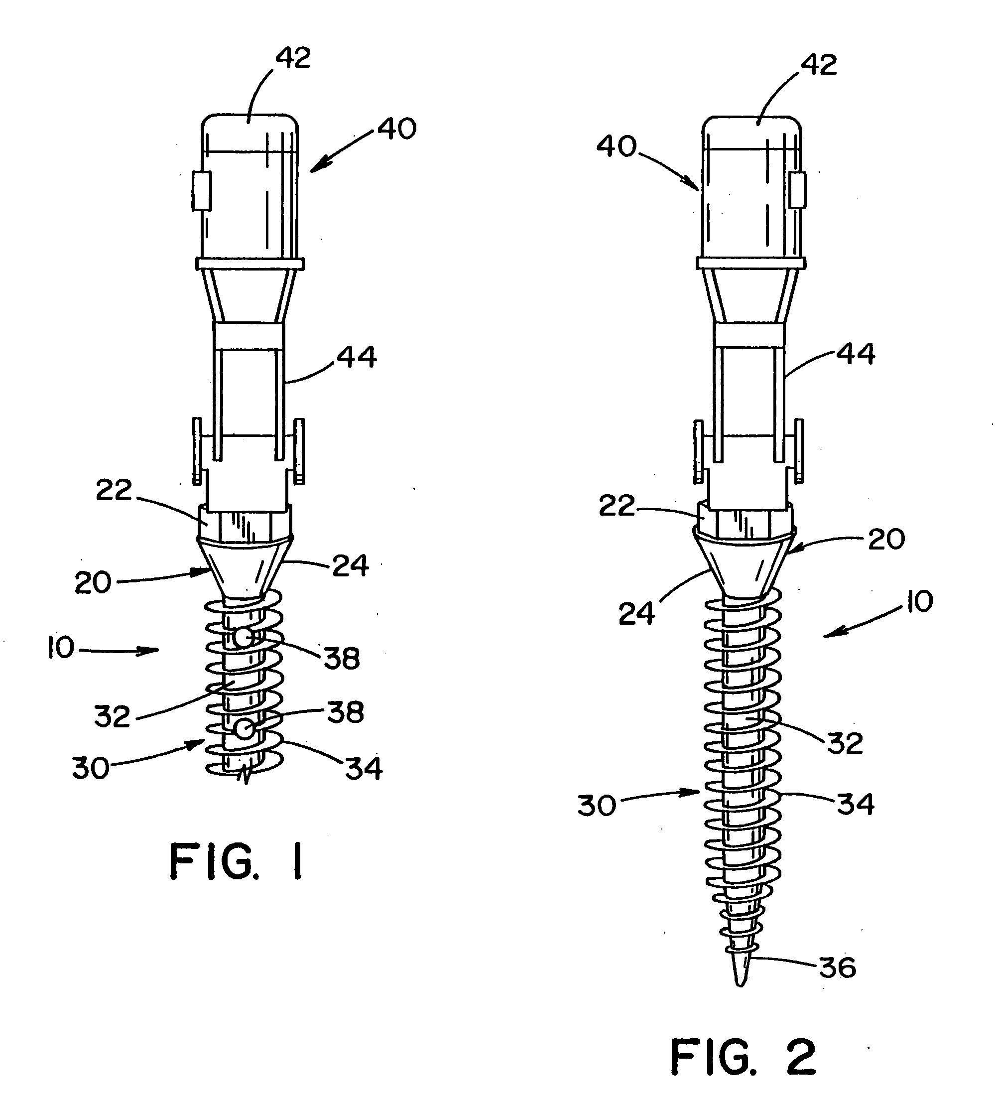
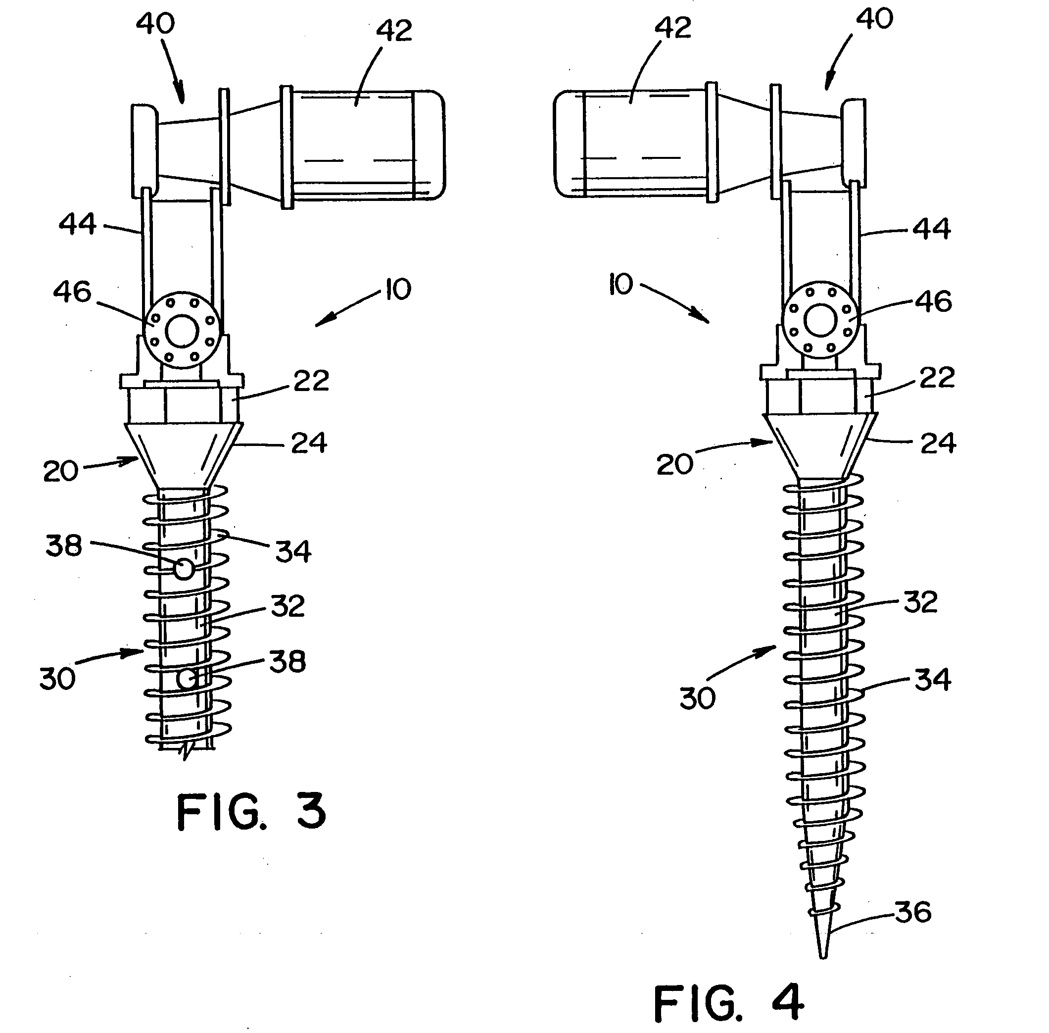
[0090] Referring to the drawings, wherein the showings are for the purpose of illustrating the preferred embodiment of the invention only and not for the purpose of limiting same, FIGS. 1-11 illustrate an implant that is disclosed in United States Patent Publication No. 2004 / 0243130, which is incorporated herein. In particular, FIG. 1 illustrates a pedicle screw 10 for insertion into bone and / or cartilage of a vertebrae. The pedicle screw is described with particular reference for use with a surgical procedure involving the vertebrae; however, it will be appreciated that the pedicle screw can be used in other regions of a body (e.g., leg, arm, hand, foot, knee, hip, pelvis, rib cage, skull, etc.) to promote healing in such regions. It will also be appreciated that the bone screw system can be used in other areas of the vertebrae such as, but not limited to, the lamina, facets, etc. It will also be appreciated that the implant can be a form other than a pedicle screw.

[0091] Pedicle ...


PUM


Abstract

An implant and sleeve combination for at least partial insertion into a bone and/or cartilage. The implant includes a lower portion and the sleeve includes a cavity designed to at least partially receive the lower portion of the implant.

Description

[0001] The present invention claims priority on U.S. Provisional Application Ser. Nos. 60 / 609,863 filed Sep. 15, 2004 and 60 / 650,872 filed Feb. 8, 2005, which are incorporated herein by reference. The present invention is a continuation-in-part of U.S. patent application Ser. No. 10 / 828,150 filed Apr. 20, 2004, which is incorporated herein by reference.[0002] The present invention pertains to prosthetic implants, and more particularly to implants that can be inserted into bone and / or cartilage. BACKGROUND OF THE INVENTION [0003] The human spine is made up of a column of thirty-three bones and their adjoining structures. The bodies of these vertebrae are connected by anterior and posterior ligaments and by discs of fibrocartilage generally known as intervertebral discs. These discs are positioned between opposite faces of adjacent vertebral bodies. This column of vertebrae and intervertebral discs forms a central axis that supports the head and torso. These vertebrae also enclose an ...

Claims


Application Information

Patent Timeline
Patent Type & Authority Applications(United States)
IPC IPC(8): A61B17/58
CPCA61B17/3472A61B17/864A61B17/8625A61B17/70
Inventor LEROUX, CLAYTON G.BISCUP, ROBERT S.
Owner SPINECO
Why Eureka
Try Eureka