
Liquid crystalline di(meth)acrylate compound, phase difference film, optical film, polarizing plate, liquid crystal panel and liquid crystal display device

a technology of liquid crystal display device and liquid crystal acrylate, which is applied in the direction of photosensitive materials, instruments, photomechanical equipment, etc., can solve the problems of deteriorating the display uniformity of liquid crystal display device and difficult thickness control, and achieve excellent productivity, high coating precision, and excellent transparency

Inactive Publication Date: 2006-02-23
NITTO DENKO CORP
View PDF4 Cites 8 Cited by
  • Summary
  • Abstract
  • Description
  • Claims
  • Application Information

AI Technical Summary

Benefits of technology

[0010] The present invention was done in view of such the prior art, and an object of the present invention is to provide a phase difference film which is excellent in transparency, is excellent in productivity without required to have an extremely high coating precision, and has better optical uniformity, and a liquid crystalline di(meth)acrylate compound which can afford such the phase difference film. In addition, another object of the present invention is to provide an optical film, a polarizing plate, a liquid crystal panel and a liquid crystal display device using this phase difference film.
[0029] According to the present invention, a phase difference film which is excellent in transparency, can suppress a variation in a retardation value, and is excellent in productivity without requiring to have an extremely high coating precision, and an optical film, a polarizing plate, a liquid crystal panel and a liquid crystal display device using this can be obtained.

Problems solved by technology

However, since the previous liquid crystal monomer has Δn greater than 0.10, when one tries to manufacture a phase difference film having a small retardation value using the liquid crystal monomer, a designed value of a thickness of a film is usually extremely small as about 1 μm, and it is extremely difficult to control a thickness.
In addition, there is a problem that a small variation in a thickness manifests a great variation in a retardation value, and this deteriorates display uniformity of a liquid crystal display device.

Method used


Image

  • Liquid crystalline di(meth)acrylate compound, phase difference film, optical film, polarizing plate, liquid crystal panel and liquid crystal display device
  • Liquid crystalline di(meth)acrylate compound, phase difference film, optical film, polarizing plate, liquid crystal panel and liquid crystal display device
  • Liquid crystalline di(meth)acrylate compound, phase difference film, optical film, polarizing plate, liquid crystal panel and liquid crystal display device

Examples


first embodiment

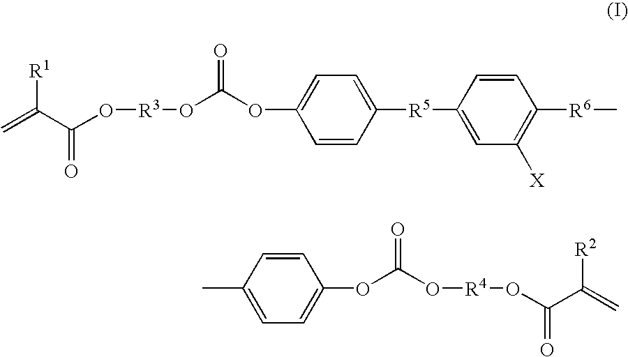
[0031] A phase difference film relating to a first embodiment of the present invention is obtained by orienting and fixing, on a substrate, a composition containing a polymerizable liquid crystal monomer (hereinafter, referred to as liquid crystal monomer (I)) of a particular structure represented by the following formula (I) not only having a carbonate structure on its main chain but also having a bromine-substituted phenylene group at a center. [0032] wherein, in the formula (I), X represents any one of Br, a halogen atom other than Br, —SMe and —SPh, R1 and R2 represent each independently a hydrogen atom or a methyl group, R3 and R4 represent each independently an alkylene group of a carbon number of 2 to 12, and R5 and R6 represent each independently —O—CO— or —CO—O—.

[0033] Such the liquid crystal monomer (I) has a structure in which an ortho position (lateral position) of a phenylene group at a central part of a main chain is substituted with any one of a bromine atom (Br), a...

second embodiment

[0083] A phase difference film relating to a second embodiment of the present invention is obtained by orienting and fixing, on a substrate, a composition containing a liquid crystalline di(meth)acrylate compound (which is a polymerizable liquid crystal monomer of a particular structure represented by the following formula (III) in which a phenylene group at a main chain central part is substituted with an acetylene group having an aromatic group (hereinafter, referred to as liquid crystal monomer (III)). [0084] wherein, in the formula (III), R1 and R2 represent each independently a hydrogen atom or a methyl group, R3 and R4 represent each independently an alkylene group of a carbon number of 2 to 12, R5 and R6 represent independently —O—CO— or —CO—O—, A1 and A2 represent each independently —O— or —O—CO—O—, and X represents an aromatic substituent.

[0085] Such the liquid crystal monomer (III) has a structure in which an ortho position (lateral position) of a phenylene group at a ma...

preparation example 1

[0162]

[0163] Two droplets of N,N-dimethylformamide were added to a mixture of bromoterephthalic acid (2.55 g, 10.4 mmol) and thionyl chloride (12.4 g, 104.2 mmol), and the mixture was stirred at 70° C. for 2 hours under nitrogen. After excessive thionyl chloride was removed under reduced pressure, dichloromethane (10 ml), a phenolic compound represented by the above chemical structural formula 1 (6.42 g, 22.9 mmol) and a small amount of BHT were added. A reactor was immersed in a water bath, 4.4 ml (31.3 mmol) of triethylamine was slowly added and, thereafter, the mixture was stirred at 40° C. for 2 hours. After completion of the reaction, 1N hydrochloric acid was added, and this was extracted with dichloromethane. The organic layer was washed with an aqueous saturated sodium chloride solution, and dried with magnesium sulfate. This was passed through a short column of “Florisil 75 to 150 μm (100 to 200 mesh)” manufactured by Wako Pure Chemical Industries, Ltd., the solvent was remo...


PUM

PropertyMeasurementUnit
thicknessaaaaaaaaaa
thicknessaaaaaaaaaa
carbon numberaaaaaaaaaa

Abstract

A phase difference film characterized in that said film is obtained by orienting and fixing, on a substrate, a composition containing a polymerizable liquid crystal monomer represented by the following formula (I): wherein, in the formula (I), X represents any one of Br, a halogen atom other than Br, —SMe and —SPh, R1 and R2 represent each independently a hydrogen atom or a methyl group, R3 and R4 represent each independently an alkylene group of a carbon number of 2 to 12, and R5 and R6 represent each independently —O—CO— or —CO—O—.

Description

BACKGROUND OF THE INVENTION [0001] 1. Field of the Invention [0002] The present invention relates to a liquid crystalline di(meth)acrylate compound, a phase difference film, an optical film, a polarizing plate, a liquid crystal panel and a liquid crystal display device. [0003] 2. Description of the Related Art [0004] A phase difference film is an optical film used for converting linearly polarized light into circularly polarized light or elliptically polarized light, or conversely converting circularly polarized light or elliptically polarized light into linearly polarized light. As a phase difference film, phase difference films obtained by stretching a polymer film such as polycarbonate and polystyrene have been previously used. [0005] However, since the polymer film has usually a thickness of about 40 to 100 μm, for example, when the film is applied to a liquid crystal display device, thinning of which is desired, a thinner phase difference film is desired. [0006] Then, as a subs...

Claims


Application Information

Patent Timeline
Patent Type & Authority Applications(United States)
IPC IPC(8): C09K19/00G02F1/13B05D5/00
CPCC09K19/2007C09K2019/0448Y10T428/10Y10T428/105Y10T428/1041C09K2323/00C09K2323/031C09K2323/035C09K19/14G02F1/13363
Inventor OOMORI, YUTAKASUGIHARA, HISAENAKANO, SHUUSAKU
Owner NITTO DENKO CORP
Learn More