Charged particle beam column and method of its operation

a charge particle and beam column technology, applied in the direction of instruments, heat measurement, machines/engines, etc., can solve the problems of locating defects (foreign particles) on patterned surfaces, and achieve the effect of improving the image resolution of the column, and increasing the effective voltage of the column

Active Publication Date: 2006-03-09
APPL MATERIALS ISRAEL LTD
View PDF19 Cites 30 Cited by
  • Summary
  • Abstract
  • Description
  • Claims
  • Application Information

AI Technical Summary

Benefits of technology

[0014] Thus, according to one aspect of the present invention, there is provided a method of controlling inspection of a sample with a charged particle beam column, the method comprising: supplying a certain negative voltage to the sample and providing an appropriate voltage supply distribution to electrodes of the charged particle beam column to increase an effective voltage of the column, while maintaining a required accelerating voltage for a charged particle beam, the method thereby providing for improvement of image resolution of the column.
[0015] According to another aspect of the invention, there is provided a method of controlling inspection of a sample with a charged particle beam column, which utilizes an objective lens, and an electrostatic lens formed by an anode, a sample under inspection and an additional electrode located between the objective lens and the sample, the method comprising: providing an appropriate voltage supply distribution to the anode, the sample and said additional electrode to thereby increase an effective voltage of the column and allow for imaging the sample with a primary charged particle beam energy landing substantially not exceeding 300 eV.
[0016] According to yet another aspect of the invention, there is provided a method of controlling inspection of a sample with a charged particle beam column to increase image resolution of the column, the method comprising: supplying a certain negative voltage to the sample; and supplying to an electrode of the lens arrangement closer to the sample a voltage that is either slightly lower or substantially equal to that of the sample, or is significantly higher than that of the sample.
[0017] According to yet another aspect of the invention, there is provided a method of controlling inspection of a sample with a charged particle beam column to increase image resolution of the column, the method comprising supplying a certain negative voltage to a sample under inspection; and supplying to an electrode of a lens arrangement of the column closer to the sa

Problems solved by technology

Another known problem of the inspection systems of the kind specified is a

Method used


Image

  • Charged particle beam column and method of its operation
  • Charged particle beam column and method of its operation
  • Charged particle beam column and method of its operation

Examples


Embodiment Construction

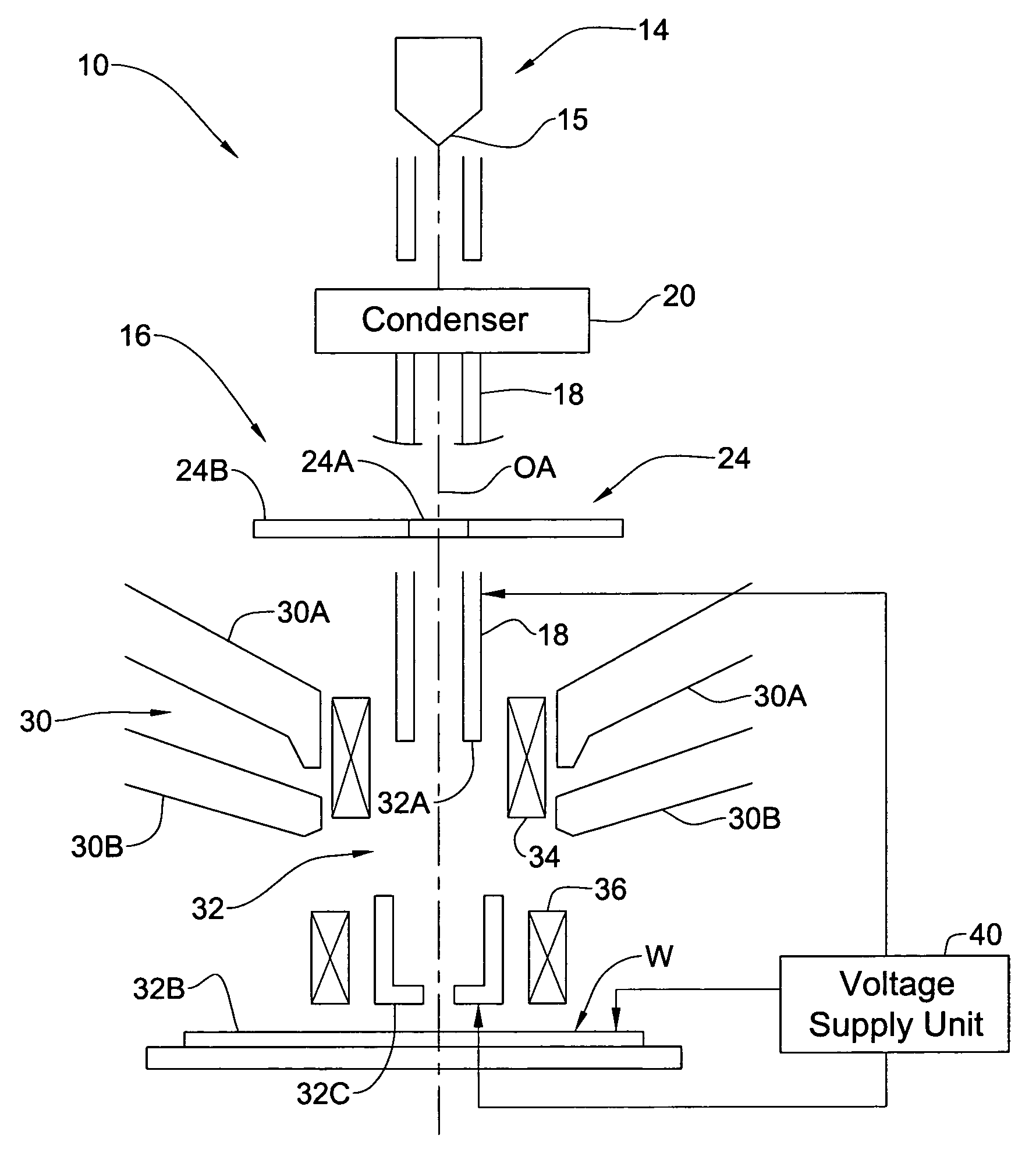
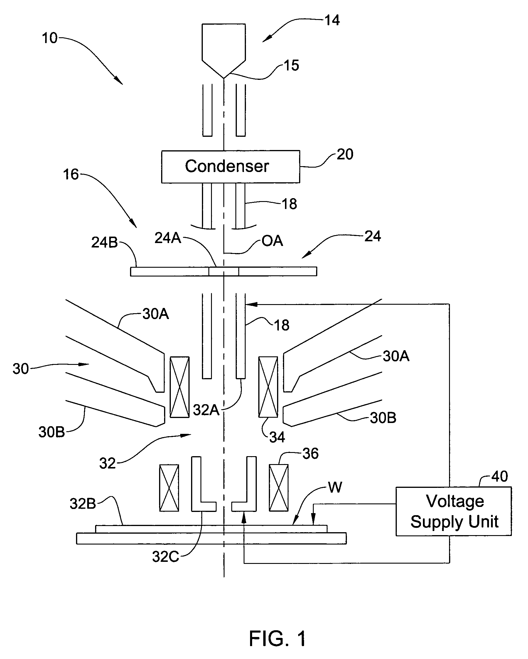
[0034] Referring to FIG. 1, there is schematically illustrated a SEM system 10 for inspecting / measuring a wafer W. The SEM system 10 typically comprises an electron beam source 14 (a so-called “electron gun”) having a small tip (cathode) 15; a charged particle beam column 16; and a secondary electrons' detector 24 The charged particle beam column 16 includes an anode tube 18 that defines a primary beam drift space; a condenser lens arrangement 20; and a focusing arrangement 22. The longitudinal axis of the anode tube 18 defines an axis OA of the primary beam propagation towards the focusing arrangement 22.

[0035] In the present example, the detector 24 is the so-called “in-column detector”, designed like a plate having an opening 24A surrounded by detecting regions 24B. The detector 24 is located such that the longitudinal axis of the anode tube 18 passes the opening 24A, which thus serves as a primary beam hole.

[0036] The column 16 also typically comprises beam blank means, severa...


PUM


Abstract

A method and system are presented for controlling inspection of a sample with a charged particle beam. A certain given voltage is supplied to an anode of the column to provide a required accelerating voltage for a charged particle beam. A certain negative voltage is supplied to the sample selected so as to provide a desirably high effective voltage of the column at said given voltage of the anode. A certain voltage is supplied an electrode of a lens arrangement located closer to the sample, this voltage being selected to satisfy one of the following conditions: the electrode voltage is either equal to or slightly lower than that of the sample; and the electrode voltage is significantly higher than that of the sample.

Description

FIELD OF THE INVENTION [0001] The present invention relates to a charged particle beam column and a method of its operation. BACKGROUND OF THE INVENTION [0002] Charged particle beam columns are typically employed in scanning electron microscopy (SEM), which is a known technique widely used in the manufacture of semiconductor wafers, being utilized in a CD metrology tool, the so-called CD-SEM (critical dimension scanning electron microscope), and a defect review SEM. In a SEM, the region of a sample to be examined is two-dimensionally scanned by means of a focused primary beam of electrically charged particles, usually electrons. Irradiation of the sample with the primary electron beam releases secondary (and / or backscattered) electrons. The secondary electrons are released at that side of the sample at which the primary electron beam is incident, and move back to be captured by a detector, which generates an output electric signal proportional to the so-detected electric current. Th...

Claims


Application Information

Patent Timeline
IPC IPC(8): G01N23/225H01J37/28
CPCG01N23/2204G01N23/2251H01J37/28H01J2237/2817H01J2237/24578H01J2237/24592H01J2237/04756
Inventor PETROV, IGORADAMEC, PAVELROSENBERG, ZVIKA
Owner APPL MATERIALS ISRAEL LTD
Why Eureka
Try Eureka