Process for producing oxygen partial pressure detecting part of resistance oxygen sensor

a technology of oxygen sensor and partial pressure, which is applied in the direction of instruments, coatings, chemistry apparatuses and processes, etc., can solve the problems of difficult to make the sensor small, poor response of the output on the oxygen partial pressure change, and complex structur

Inactive Publication Date: 2006-03-16
NAT INST OF ADVANCED IND SCI & TECH
View PDF5 Cites 5 Cited by
  • Summary
  • Abstract
  • Description
  • Claims
  • Application Information

AI Technical Summary

Benefits of technology

[0008] In view of the prior art described above, it is an object of the present invention to thoroughly resolve the problems thereof, and provide a porous thick film of cerium oxide or an oxide having cerium oxide as a principal component thereof that has extremely few cracks and can be satisfactorily used as an oxygen partial pressure detecting part of an oxygen sensor, and a method of manufacturing such a porous thick film. Moreover, ideally, it is an object of the present invention to provide a method of manufacturing a porous thick film having an average particle diameter of not more than 200 nm.
[0023] Next, the paste is printed onto a substrate by screen printing. Here, an insulating material is used for the substrate. Preferable examples include alumina, magnesia and quartz, but there is no limitation thereto. Next, calcination is carried out at 300 to 600° C., thus removing the organic binder. As the calcination atmosphere, air, or an oxidizing atmosphere such as oxygen is preferable. This step can be omitted in the case that the rate of temperature increase in the subsequent sintering step is set to be gradual. Finally, sintering is carried out at 1000 to 1200° C., whereby an oxygen partial pressure detecting part of a resistive oxygen sensor is obtained. The sintering atmosphere may be any of air, an oxidizing atmosphere such as or oxygen, or a reducing atmosphere such as hydrogen or carbon monoxide. Through the sintering, necks are produced between the fine particles to form a porous body, which is electrically conductive. The average particle diameter preferably becomes 50 to 200 nm, more preferably 50 to 100 nm. The porous thick film obtained through the above manufacturing method has extremely few cracks, and can be satisfactorily used as an oxygen partial pressure detecting part of an oxygen sensor; specifically, the electrical conductivity is at least 10−3 S / m at 800° C., an excellent oxygen partial pressure dependence is exhibited, and the response speed is also excellent.

Problems solved by technology

With this type of sensor, the difference in the oxygen partial pressure between a reference electrode and a measuring electrode is measured as an electromotive force, and hence a reference electrode is required; there has thus been a problem that the structure is complex, and it is difficult to make the sensor small.
However, with such a resistive oxygen gas sensor, there has been a problem that the responsiveness of the output upon the oxygen partial pressure changing is poor (see, for example, Japanese Patent Application Laid-open No.
Moreover, titanium oxide has been used as the oxide semiconductor of resistive oxygen gas sensors, but this material has had the problem of being poor in terms of durability and stability.
However, with the spray pyrolysis method, there has been a problem that the amount of powder manufactured per unit time is low.
However, a powder obtained using this method is extremely fine, and moreover the fine particles are agglomerated; in the case of manufacturing a porous thick film from a paste in which such a powder and a vehicle (organic binder) are merely mixed together, there is thus a problem that there are many cracks, and hence the resistance of the thick film increases.
It is undesirable for the resistance to increase, since then the measuring circuitry for measuring the resistance becomes complex.
Moreover, there is a problem that in the case that the cracks are very severe, there is no electrical conductivity, and hence use as an oxygen sensor is not possible, and moreover there has also been a problem that the thick film readily peels away from the substrate because of the cracks.

Method used


Image

  • Process for producing oxygen partial pressure detecting part of resistance oxygen sensor
  • Process for producing oxygen partial pressure detecting part of resistance oxygen sensor
  • Process for producing oxygen partial pressure detecting part of resistance oxygen sensor

Examples


example 1

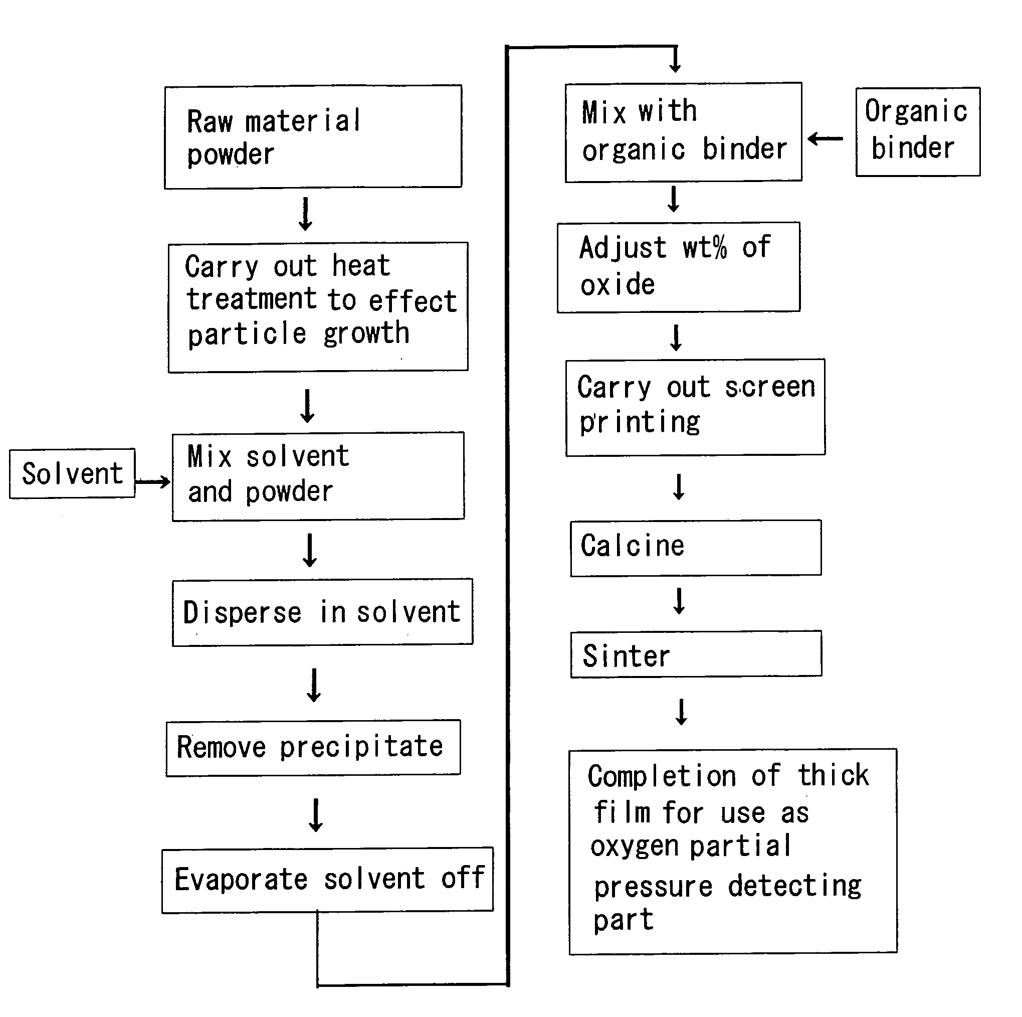
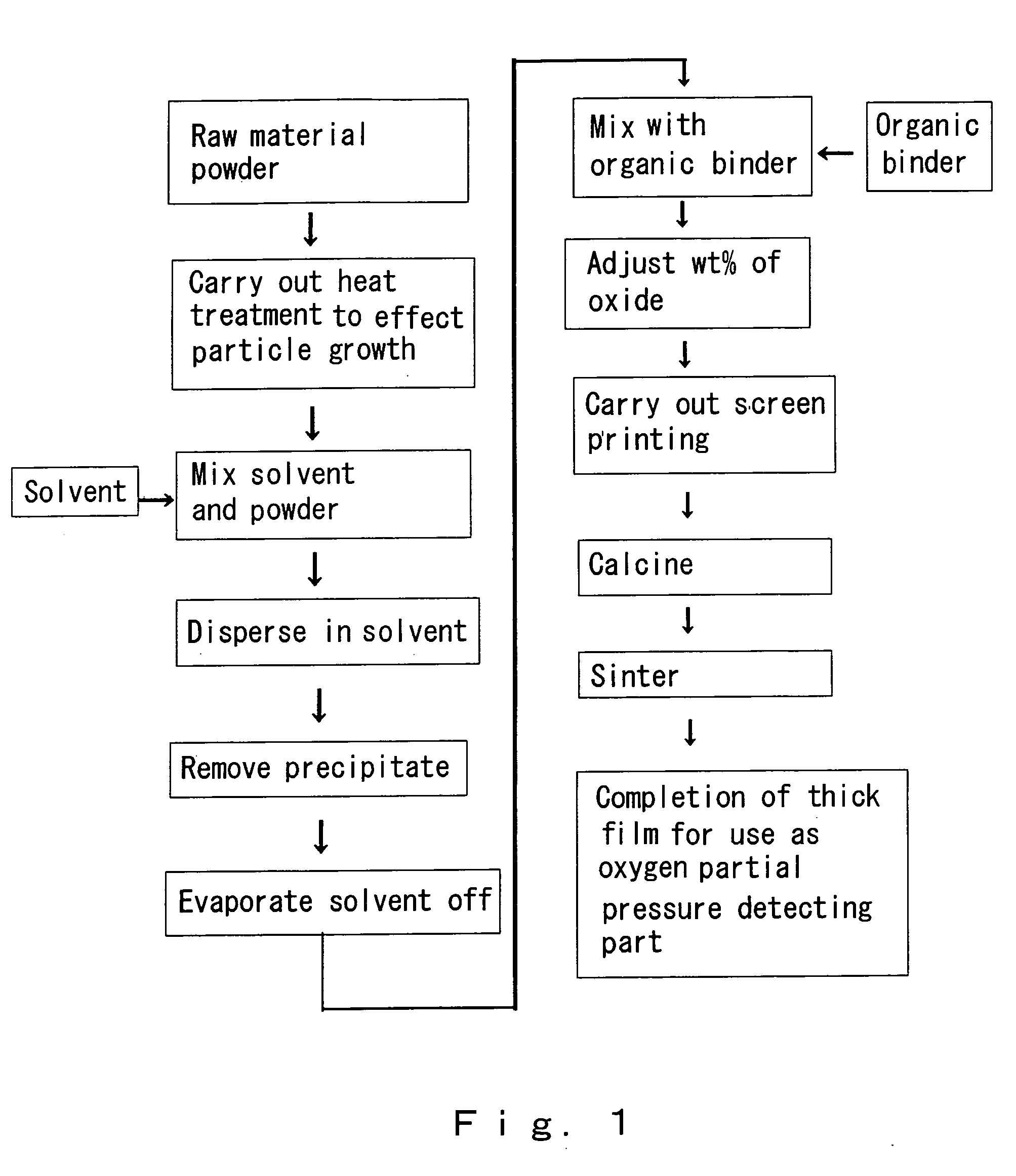
[0039] In the present example, a powder comprising cerium oxide fine particles obtained through a precipitation method was used as a raw material. Briefly describing the method of preparing the powder using the precipitation method, first a cerium nitrate aqueous solution was prepared. Next, ammonia water was added, whereby a precipitate was produced. This precipitate was mixed with carbon, and heated for 4 hours at 600° C. in air, thus obtaining the powder. Scanning electron microscope (SEM) photomicrographs of the powder (the raw material before the heat treatment step) are shown in FIGS. 2 and 3. The raw material had a particle diameter of 10 to 20 nm, and was agglomerated. Next, as a pretreatment step, the powder was subjected to heat treatment for 4 hours at 900° C. in air. An SEM photomicrograph of the raw material after this step is shown in FIG. 4. Particle growth occurred, the average particle diameter becoming 48 nm.

[0040] Next, ethanol was added as a solvent in a proport...

example 2

[0046] A powder comprising cerium oxide fine particles obtained through a precipitation method was used as a raw material, and the heat treatment temperature in the pretreatment was made to be 950° C.; an SEM photomicrograph of the powder in this case is shown in FIG. 12. Particle growth has occurred to over 100 nm. It was thus found that in the case of manufacturing a thick film for which the average particle diameter of the ultimately obtained thick film is to be 100 nm, a sintering temperature in the pretreatment step of 950° C. is too high.

example 3

[0047] In the present example, a powder was prepared using the following procedure. First, a cerium nitrate aqueous solution was prepared. Next, ammonia water was added, whereby a precipitate was produced. This precipitate was mixed with carbon, and heated for 4 hours at 900° in air, thus obtaining the powder. In this heat treatment step, the heat treatment step for changing the precipitate containing the hydroxide, water and soon into the oxide and the heat treatment step for effecting particle growth were carried out consecutively. The powder was then mixed with ethanol, and then a thick film was manufactured using the same method as in Example 1. The wt % of the oxide contained in the paste was made to be 20 wt %. The porous thick film manufactured in this way contained hardly any cracks, and hence it was found even if the heat treatment step for changing the precipitate containing the hydroxide, water and so on into the oxide and the heat treatment step for effecting particle gr...


PUM

PropertyMeasurementUnit
particle diameteraaaaaaaaaa

Abstract

The present invention provides a method of manufacturing a porous thick film of an oxide that has extremely few cracks and can be satisfactorily used as an oxygen partial pressure detecting part of an oxygen sensor. The present invention relates to a method of manufacturing such a porous thick film as an oxygen partial pressure detecting part of a resistive oxygen sensor comprising taking a fine particle powder of an oxide containing cerium oxide as a raw material powder, preparing a paste containing the oxide, printing the paste onto a substrate by screen printing, calcining and sintering, the method comprising a step of carrying out heat treatment to effect particle growth from the average particle diameter of the raw material powder to a particle diameter less than the average particle diameter of the ultimately obtained thick film, a step of mixing the particle growth-effected powder with a solvent, a step of dispersing agglomerated particles in the solvent, a step of removing a precipitate, a step of evaporating off the solvent, and a step of mixing the resulting oxide with an organic binder to obtain the paste.

Description

BACKGROUND OF THE INVENTION [0001] 1. Field of the Invention [0002] The present invention relates to a method of manufacturing a porous thick film to be used in an oxygen partial pressure detecting part of a resistive oxygen sensor, and more specifically relates to a cerium oxide-based porous thick film as an oxygen partial pressure detecting part of an oxygen sensor that measures oxygen partial pressure and is used in an air-fuel ratio feedback control system for controlling the air-fuel ratio in the exhaust gas of an automobile or the like, so as to improve the exhaust gas purification rate and the fuel efficiency, and a method of manufacturing the cerium oxide-based porous thick film. Here, the air-fuel ratio is the ratio of air to fuel, there being a one-to-one relationship between the oxygen partial pressure and the air-fuel ratio. [0003] 2. Description of the Related Art [0004] Hitherto, as oxygen gas sensors for automobiles and the like, solid electrolyte ones have predominan...

Claims


Application Information

Patent Timeline
Patent Type & Authority Applications(United States)
IPC IPC(8): B05D3/02C08J7/04C01F17/00G01N27/12
CPCG01N27/125
Inventor IZU, NORIYASHIN, WOOSUCKMATSUBARA, ICHIROMURAYAMA, NORIMITSUYAMAUCHI, YUKIHIKOKANZAKI, SHUZO
Owner NAT INST OF ADVANCED IND SCI & TECH
Why Eureka
Try Eureka