Optical detection of label-free biomolecular interactions using microreplicated plastic sensor elements

a technology of plastic sensor elements and optical detection, which is applied in the field of optical detection of label-free biomolecular interactions using micro-replicated plastic sensor elements, can solve the problems that methods have yet to yield commercially available high-throughput instruments, and achieve the effect of inexpensive incorporation

Inactive Publication Date: 2006-03-16
X BODY
View PDF98 Cites 102 Cited by
  • Summary
  • Abstract
  • Description
  • Claims
  • Application Information

AI Technical Summary

Benefits of technology

[0039] Still another embodiment of the invention provides a method of detecting an interaction of a first molecule with a second test molecule. The method comprises applying a mixture of the first and second molecules to a distinct location on a biosensor, wherein the biosensor comprises an optical grating and a substrate layer that supports the optical grating; and wherein, when the biosensor is illuminated a resonant grating effect is produced on the reflected radiation spectrum, and wherein the depth and period of the optical grating are less than the wavelength of the resonant grating effect; applying a mixture of the first molecule with a third control molecule to a distinct location on the biosensor or a similar biosensor, wherein the third control molecule does not interact with the first molecule, and wherein the third control molecule is about the same size as the first molecule; and detecting a shift in the reflected wavelength of light from the distinct locations. Wherein, if the shift in the reflected wavelength of light from the distinct location to which a mixture of the first molecule and the second test molecule was applied is greater than the shift in the reflected wavelength from the distinct location to which a mixture of the first molecule with the third control molecule was applied, then the first molecule and the second test molecule interact. The first molecule can be selected from the group consisting of a nucl

Problems solved by technology

With the completion of the sequencing of the human genome, one of the next grand challenges of molecular biology will be to understand how the many protein targets encoded by DNA interact with other proteins, small molecule pharmaceutical candidates, and a large host of enzymes and inhibitors.
However, to date, these metho

Method used


Image

  • Optical detection of label-free biomolecular interactions using microreplicated plastic sensor elements
  • Optical detection of label-free biomolecular interactions using microreplicated plastic sensor elements
  • Optical detection of label-free biomolecular interactions using microreplicated plastic sensor elements

Examples


example 1

Fabrication of a SWS Biosensor

[0216] An example of biosensor fabrication begins with a flat glass substrate that is coated with a thin layer (180 nm) of silicon nitride by plasma-enhanced chemical vapor deposition (PECVD).

[0217] The desired structure is first produced in photoresist by coherently exposing a thin photoresist film to three laser beams, as described in previously (Cowen, “The recording and large scale replication of crossed holographic grating arrays using multiple beam interferometry,” in International Conference on the Application, Theory, and Fabrication of Periodic Structures, Diffraction Gratings, and Moire Phenomena II, J. M. Lerner, ed., Proc. Soc. Photo-Opt. Instrum. Eng., 503, 120-129, 1984; Cowen, “Holographic honeycomb microlens,”Opt. Eng. 24, 796-802 (1985); Cowen & Slafer, “The recording and replication of holographic micropatterns for the ordering of photographic emulsion grains in film systems,”J. Imaging Sci. 31, 100-107, 1987. The nonlinear etching ...

example 2

[0218] A SRVD biosensor was prepared by making five circular diffuse grating holograms by stamping a metal master plate into vinyl. The circular holograms were cut out and glued to glass slides. The slides were coated with 1000 angstroms of aluminum. In air, the resonant wavelength of the grating is ˜380 nm, and therefore, no reflected color is visible. When the grating is covered with water, a light blue reflection is observed. Reflected wavelength shifts are observable and measurable while the grating is covered with a liquid, or if a specific binding substances and / or binding partners cover the structure.

[0219] Both proteins and bacteria were immobilized onto the surface of a SRVD biosensor at high concentration and the wavelength shift was measured. For each material, a 20 μl droplet is placed onto a biosensor distinct location and allowed to dry in air. At 1 μg / ml protein concentration, a 20 μl droplet spreads out to cover a 1 cm diameter circle and deposits about 2×10⁻⁸ grams...

example 3

Computer Model of Biosensor

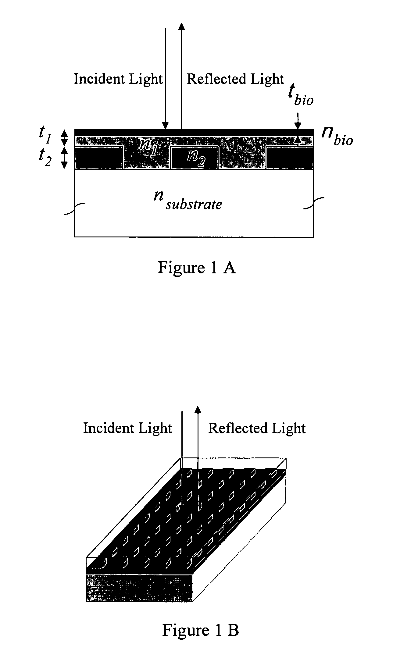
[0227] To demonstrate the concept that a resonant grating structure can be used as a biosensor by measuring the reflected wavelength shift that is induced when biological material is adsorbed onto its surface, the structure shown in FIG. 1 was modeled by computer. For purposes of demonstration, the substrate chosen was glass (nsubstrate=1.50). The grating is an optical pattern of silicon nitride squares (t2=180 nm, n2=2.01, k2=0.001) with a period of 510 nm, and a filling factor of 56.2% (i.e. 56.2% of the surface is covered with silicon nitride squares while the rest is the area between the squares). The areas between silicon nitride squares are filled with a lower refractive index material. The same material also covers the squares and provides a uniformly flat upper surface. For this simulation, a glass layer was selected (n1=1.40) that covers the silicon nitride squares by t2=100 nm. To observe the effect on the reflected wavelength of this structure...


PUM

PropertyMeasurementUnit
Angleaaaaaaaaaa
Angleaaaaaaaaaa
Diameteraaaaaaaaaa

Abstract

Methods and compositions are provided for detecting biomolecular interactions. The use of labels is not required and the methods can be performed in a high-throughput manner. The invention also provides optical devices useful as narrow band filters.

Description

PRIORITY [0001] This application is a continuation-in-part of U.S. appl. Ser. No. 10 / 058,626, filed Jan. 28, 2002, which is a continuation-in-part of U.S. appl. Ser. No. 09 / 930,352, filed Aug. 15, 2001, which claims the benefit of U.S. provisional application 60 / 244,312 filed Oct. 30, 2000; U.S. provisional application 60 / 283,314 filed Apr. 12, 2001; and U.S. provisional application 60 / 303,028 filed Jul. 3, 2001, all of which are hereby incorporated by reference.TECHNICAL AREA OF THE INVENTION [0002] The invention relates to compositions and methods for detecting biomolecular interactions. The detection can occur without the use of labels and can be done in a high-throughput manner. The invention also relates to optical devices. BACKGROUND OF THE INVENTION [0003] With the completion of the sequencing of the human genome, one of the next grand challenges of molecular biology will be to understand how the many protein targets encoded by DNA interact with other proteins, small molecule...

Claims


Application Information

Patent Timeline
IPC IPC(8): C12M1/34B01L3/00G01N21/25G01N21/47G01N33/543G02B5/18
CPCB01L3/5085Y10S436/805B01L2300/0654B01L2300/0829G01N21/253G01N21/4788G01N21/7743G01N33/54373G02B5/1809G02B5/1852G02B6/02061Y10S436/813Y10S435/808Y10S436/807Y10S436/811Y10S436/809B01L2300/0636
Inventor CUNNINGHAM, BRIAN T.PEPPER, JANELIN, BOLI, PETERPIEN, HOMERQIU, JEAN
Owner X BODY
Why Eureka
Try Eureka