High speed microscope with three-dimensional laser beam scanning

a laser beam scanning and high-speed microscope technology, applied in the direction of discharge tube/lamp details, instruments, optical elements, etc., can solve the problems of limiting the speed of such systems, raster scanning nor random access to multiple sites-of-interest at the required rate, and reducing resolution, reducing the time dependence of deflection angl

Inactive Publication Date: 2006-04-06
BAYLOR COLLEGE OF MEDICINE
View PDF1 Cites 42 Cited by
  • Summary
  • Abstract
  • Description
  • Claims
  • Application Information

AI Technical Summary

Benefits of technology

[0016] In addition, embodiments of the present invention rely on continuously changing the frequency of the acoustic wave in the AO medium, a process which is known as ‘chirping’. If the change in frequency is linear with time, the resulting angles of deflection at any particular time are similar to those for a cylindrical lens, but the axis of the deflection is also time-varying. The use of two AODs, in which the acoustic propagation directions are reversed, removes the time dependence of the deflection angle, and allows for a symmetrical cylindrical effect. Therefore, the collimation of a light beam can be controlled and the axial position of a focus spot can be varied.
[0017] Furthermore, embodiments of the present invention allow for independent control of lateral scanning with a light beam. As discussed in more detail below, control of the lateral scanning is accomplished by offsetting the frequencies of the acoustic waves that are passed through the AODs. The frequencies are offset such that for a given point in time and a given position on the AOD, the acoustic waves will have different frequencies. The ability to simultaneously and independently control both the lateral and axial position of a light beam focal point, through the use of counter-propagating acoustic waves with offset frequencies, provides for numerous benefits, including fast

Problems solved by technology

The scanning principle generally employed is mechano-optical, i.e. galvanometer-driven mirrors; thus, inertia limits the speed of such systems.
Therefore, while confocal and multi-photon microscopy have proven to be extremely useful in obtaining structural images, success of these techniques with functional imaging such as optical recording of neuronal activity has been limited, as neither raster-scanning nor random-access of multiple sites-of-interest is possible at the required rates.
While video-rate imaging with multiphoton microscopy has been documented using resonant galvanometers or micro-lens arrays, neither of these support high-speed functional imaging.
In general, existing confocal and multi-photon microscopes lack the spatio-temporal resolution necessary to measure fast multi-site optical signals from small brain structures.
Due to these constraints in scan patterns most microscopes cannot follow complex shaped biological structures such as neuronal dendrites.
In addition to the limited flexibility of lateral scan pattern, fast functional imaging of three-dimensional structures is practically impossible due to the low focusing speed of microscopes.
However, even these linear motors require axial step times (>10 ms) that are significantly longer per change of focus plane than the total time available to scan the entire volume-of-interest (<1 ms) containing many such planes.
Even if faster methods to axially position the objective lens were available, resulting complications such as shock waves in the immersion solution would make these attempts fail because of movement artifacts interfering with delicate living tissue and patch-clamp seals
While the inherent sectioning ability, in combination with low levels of photodamage, provided by MPLSM has made it extremely useful for the structural imaging of small process

Method used


Image

  • High speed microscope with three-dimensional laser beam scanning
  • High speed microscope with three-dimensional laser beam scanning
  • High speed microscope with three-dimensional laser beam scanning

Examples


Embodiment Construction

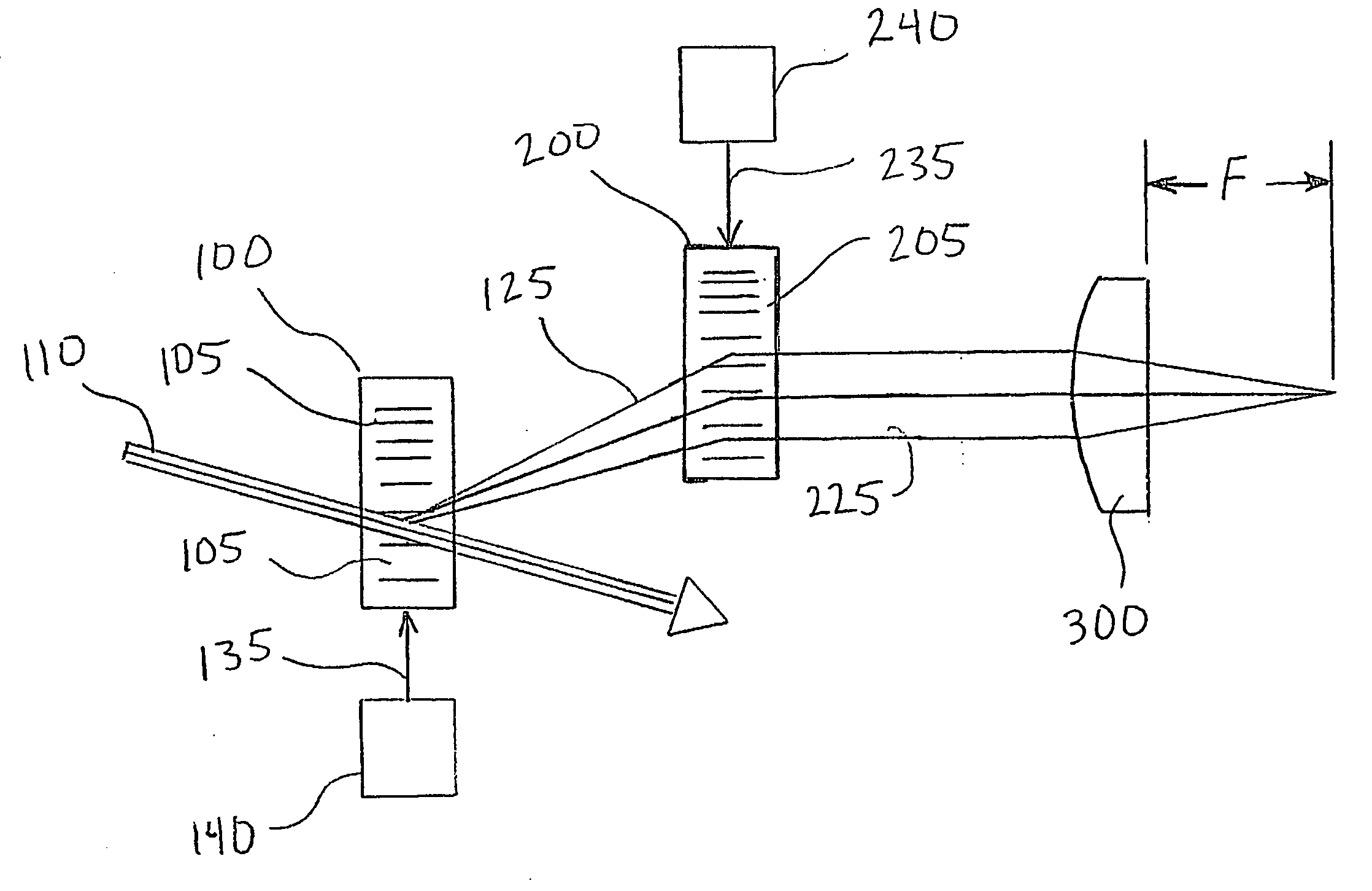
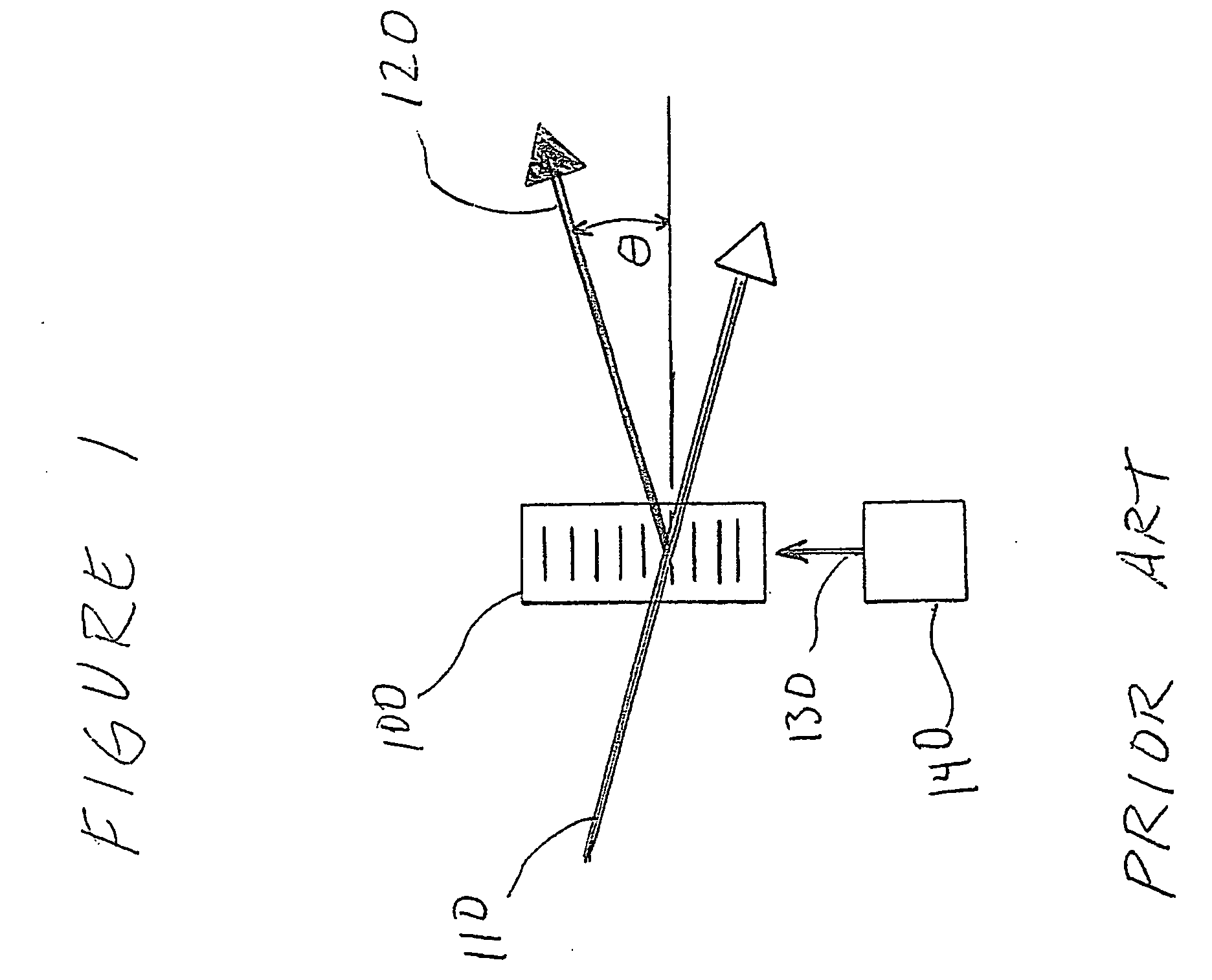
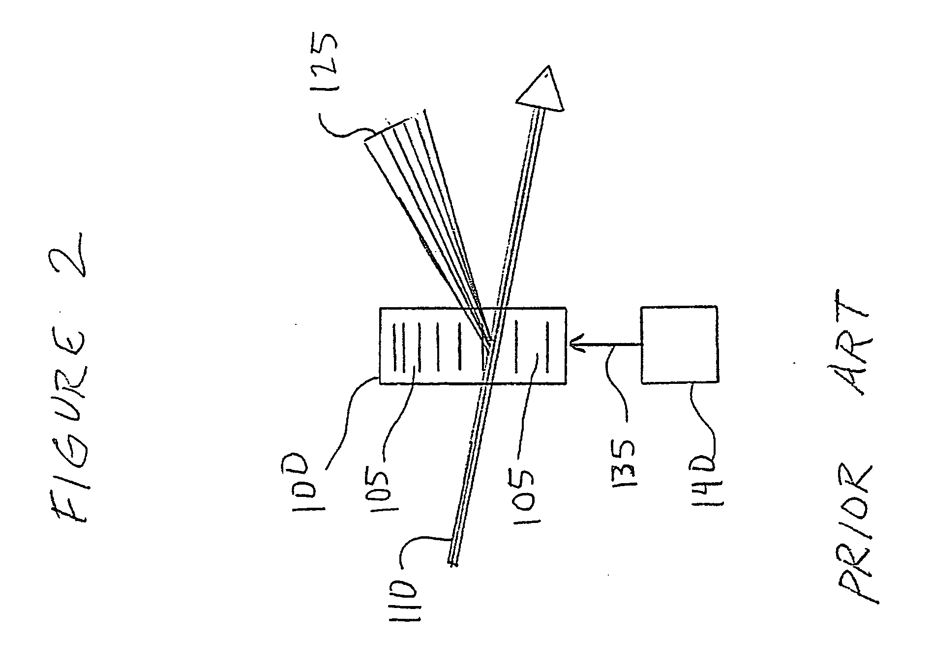
[0014] Preferred embodiments of the present invention comprise a scanning device to direct the focus of a light beam (such as a laser) to multiple predefined positions within a given volume. Preferred embodiments comprise an acousto-optically controlled light diffraction to independently change both collimation and direction of a laser beam. This inertia-free mechanism allows for very fast (microsecond range) three-dimensional positioning of the focus spot.

[0015] Embodiments of the present invention comprise a novel instrument for both structural and functional imaging studies of specimens such as living brain tissue. Certain embodiments use four AODs together with a commercial objective lens to deterministically and quickly (˜30 μs) position the focus spot in a microscopic 3D volume via a remote focusing strategy, while other embodiments may use fewer AODs with multiple acoustic waves in an individual AOD. Embodiments of the present invention utilize counter-propagating acoustic w...


PUM


Abstract

A system and method for independently controlling the collimation and lateral positioning of a light beam comprises at least one acousto-optic deflector and a pair of counter propagating acoustic waves with offset frequencies. While the frequency offset controls the lateral positioning of the light beam, a frequency gradient across the acousto-optic deflectors controls the collimation of the light beam.

Description

CROSS-REFERENCE TO RELATED APPLICATIONS [0001] The present application claims the benefit of U.S. Provisional Application Ser. No. 60 / 616,432, filed Oct. 6, 2004, entitled High Speed Microscope With Three-Dimensional Laser Beam Scanning, which is incorporated herein by reference.SPONSORED RESEARCH OR DEVELOPMENT [0002] This invention was made with government support under Grant No. DBI-0130852 awarded by the National Science FoundationBACKGROUND OF THE INVENTION [0003] 1. Field of the Invention [0004] The present invention generally relates to three-dimensional scanning with a light beam such as a laser. More particularly, the invention relates to high speed microscopy with three-dimensional laser beam scanning. [0005] 2. Description of Related Art [0006] In experimental biology, increasing numbers of studies that are carried out on the cellular or sub-cellular level apply optical imaging techniques for combined structural and functional analysis of live nerve cells. Optical imaging...

Claims


Application Information

Patent Timeline
IPC IPC(8): G02B27/40
CPCG02B21/002G02B21/006G02B26/0808G02B27/30G02F1/33G02F2201/16
Inventor SAGGAU, PETERREDDY, DUEMANIIYER, VIJAY
Owner BAYLOR COLLEGE OF MEDICINE
Why Eureka
Try Eureka