Pressure regulated continuously variable volume container for fluid delivery

a technology of continuous variable volume and container, which is applied in the direction of laboratory glassware, instruments, and analysis using chemical indicators, can solve the problems of significant loss of chromatograph operating time or loss in whole or in part of unpurified mixed particle(s), significant problem of establishing and maintaining consistency, and contamination of fluid, so as to eliminate exposure

Inactive Publication Date: 2006-06-08
XY
View PDF25 Cites 72 Cited by
  • Summary
  • Abstract
  • Description
  • Claims
  • Application Information

AI Technical Summary

Benefits of technology

[0027] Accordingly, a broad object of the invention can be to eliminate exposure of fluid(s) being delivered to the flow path of a microfluidic device or chromatography systems to external sources of contamination. One aspect of this object of the invention can be to isolate the fluids being delivered to the flow path of a microfluidic device from moving toward equilibrium with atmospheric gases, mixtures of gases, or partial pressures of gases whether at atmospheric pressure or at greater than atmospheric pressures. A second aspect of this ob

Problems solved by technology

Any inaccuracy in the preparation of such fluids can lead to significant loss of chromatograph operating time or loss in whole or in part of the unpurified mixed particle(s) or population(s) of particles or of the purified individual particle(s) or subpopulation(s) of particles of interest.
Nonetheless, significant problems remain unresolved with regard to establishing and maintaining consistency in the preparation, handling, and delivery of fluids to and in the conduits of such microfluidic devices.
A significant problem with conventional delivery of fluids to microfluidic devices can be contamination of the fluid.
In this way, the surfaces of the pump body can become a source of contamination to the subsequent volume of fluid transferred through the pump body.
However, peristaltic pumps have disadvantages in that they may not build very high pressures, may tend to create oscillating hydrostatic pressure variations, may be expensive to build and maintain, and recurring peristalsis of the conformable conduit can cause progressive deformation or degradation of the conduit material which can shed, bleed, or leach into the fluid.
Another significant problem with conventional delivery of fluids to microfluidic devices can be the use of a gas or mixtures of gases, such as air, argon, nitrogen, helium, or the like, to pressurize the head space of a fluid reservoir to initiate and maintain a fluid stream in the conduits of the microfluidic device.
Use of pressurized gas(es) or atmospheric gas pressure in contact with fluid in the reservoir can result in bubble formation in the fluid paths of the device.
Since microfluidic devices have small diameter flow paths and the biological particles entrained in the fluid stream are also of small size, even very small or fine bubbles formed in the flow path can affect volume and laminar flow of the fluid within the flow paths, can cause failure of certain types of pumps, and can result in analytical errors.
Even bubbles invisible to the naked eye can be problematic with respect to the proper performance of a microfluidic device.
When pressurized gas enters the flow path of a microfluidic device directly, the bubbles can be much larger and in certain circumstances can interrupt of the flow of fluid all together, alter flow characteristics, or remain located in the flow path of the microfluidic device.
If the microfluidic device or flow path is not disposable, a significant amount of time may be needed to dislodge or flush unwanted bubbles from the flow path.
Another problem related to the use of pressurized gas in contact with liquids to generate a fluid stream in microfluidic devices can be an increased

Method used


Image

  • Pressure regulated continuously variable volume container for fluid delivery
  • Pressure regulated continuously variable volume container for fluid delivery
  • Pressure regulated continuously variable volume container for fluid delivery

Examples


example 1

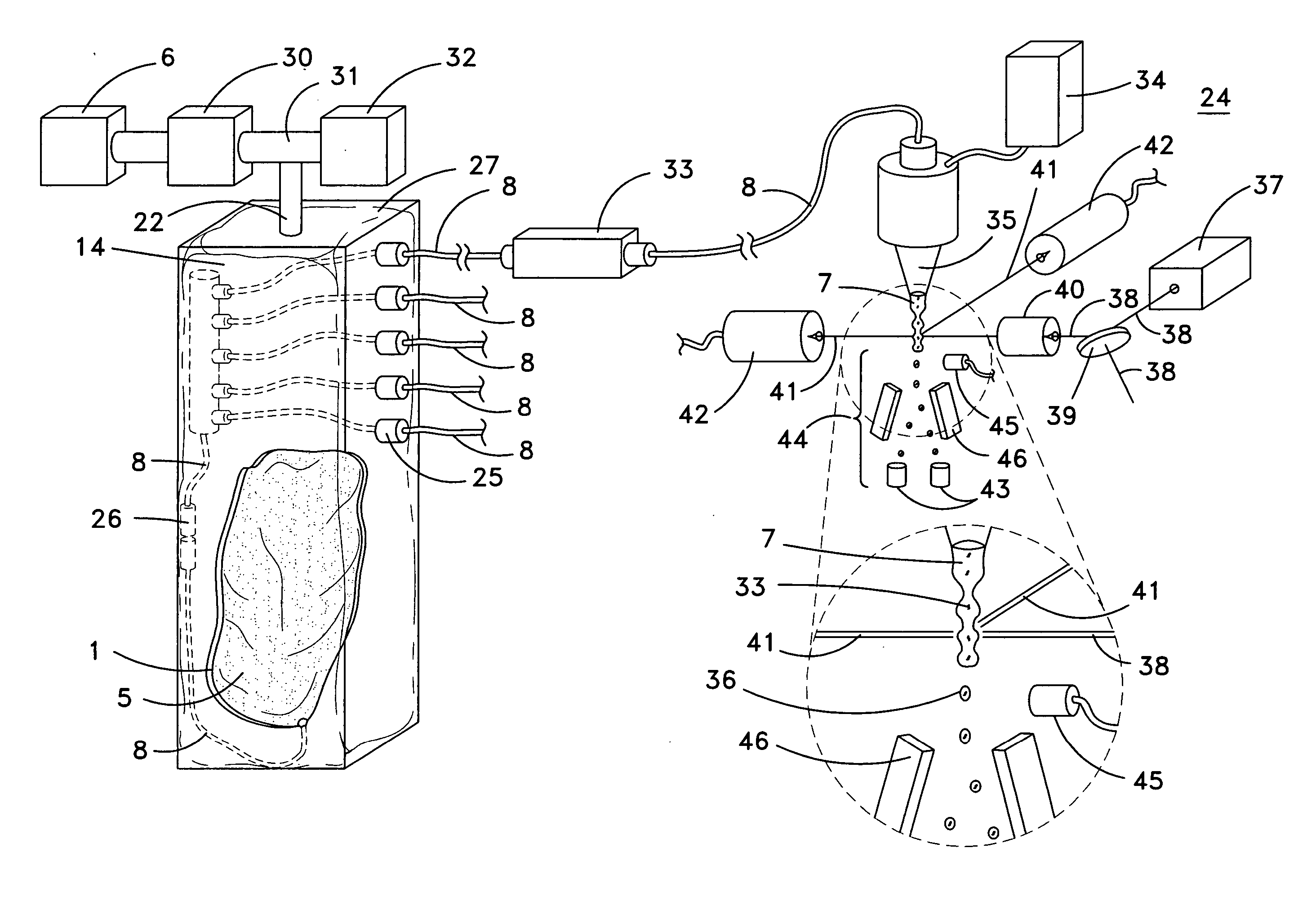
[0078] Now referring to FIG. 8, which shows a bivariate plot generated from the analysis of fluorochrome stained sperm cells differentiated based upon the presence of an X-chromosome or a Y-chromosome utilizing a DakoCytomation, Inc., MoFlo® flow cytometer in accordance with the invention. A conventional sheath fluid tank was retrofitted with a variable volume container in accordance with the invention containing about 5 liters of sterile sheath fluid. The sheath fluid was maintained at about 20° C. during use. An amount of gas was delivered to the sealed sheath fluid tank to exert an amount of gas pressure on the exterior surface of the variable volume container resulting in the generation of a fluid stream within the flow path of a DakoCytomation, Inc., MoFlo® flow cytometer. The flow cytometer was then otherwise operated in accordance with the standard operation procedures provided by DakoCytomation, Inc. for a period of about 8 hours to analyze and sort a mixture of sperm cells ...

example 2

[0079] Similarly, a flow cytometer sorting human sperm in accordance with the invention can provide X-chromosome bearing and Y-chromosome bearing populations for the purpose of sex selected artificial insemination. Human sperm cells sufficient for artificial insemination of a human female can be flow sorted in approximately 2 hours from male human ejaculate. The enriched X-chromosome bearing or Y-chromosome bearing sperm cell populations are typically over 80% pure. Clinical procedures may require that after each sample is sorted, the sorting fluidic channels are washed with an acid wash, a base wash, a disinfectant wash, and then a water wash. The instant invention can be used to deliver four different sterile fluids to the flow cytometer, and allows computer automated cleaning steps to be performed between patients. During the automated wash procedure, the physician may perform the artificial insemination procedure.

example 3

[0080] In accordance with the invention, a plurality of different microfluidic devices can be operating 24 hours per day. The variable volume containers can be located in common receptacle pressured at about 1.6 atmospheres. Each microfluidic device can be served with one or more conduits from the variable volume containers which communicate with the conventional hardware of the microfluidic device.

[0081] As can be easily understood from the foregoing, the basic concepts of the present invention may be embodied in a variety of ways. The invention involves numerous and varied embodiments of a continuously variable volume container for fluid delivery and methods of making and using such continuously variable volume container.

[0082] As such, the particular embodiments or elements of the invention disclosed by the description or shown in the figures accompanying this application are not intended to be limiting, but rather exemplary of the numerous and varied embodiments generically en...


PUM


Abstract

A fluid handling and delivery system useful in generating a fluid stream in the flow path of microfluidic device.

Description

I. BACKGROUND [0001] A pressure regulated continuously variable volume container for the handling and delivery of fluids. Specifically, a pressure regulated variable volume container useful in generating a fluid stream in the flow path of various types of microfluidic devices such as flow cytometers or liquid chromatographs. [0002] Flow cytometry, liquid chromatography, and other microfluidic devices are prominent tools used in basic and applied research and in commercial manufacturing processes. These microfluidic systems are routinely used to analyze, separate, isolate, or purify biological particles, such as cells, organelles, chromosomes, deoxyribonucleic acids (DNA), ribonucleic acids (RNA), DNA fragments, RNA fragments, proteins, protein fragments, peptides, oligonucleotides, or the like. [0003] Specifically with respect to applications in flow cytometry or the utilization of flow sort devices, biological particles, such as cells (which may be modified with one or a plurality ...

Claims


Application Information

Patent Timeline
IPC IPC(8): G01N35/08F16K17/40B01L3/00
CPCB01L3/0296Y10T436/2575B01L2200/027B01L2200/0684B01L2200/141B01L2400/0481G01N15/1484G01N35/1095G01N2015/149G01N2015/1409G01N2015/1481Y10T436/117497Y10T436/11Y10T436/118339B01L3/5027Y10T137/0318Y10T137/1624
Inventor NEAS, EDWIN DEANKUIKEN, JERALD EDWARDSCHENK, JOHN LOUISGILLIGAN, THOMAS BOYD
Owner XY
Why Eureka
Try Eureka