
Method for preparing synthesis gas, method for preparing dimethyl ether using synthesis gas, and furnace for preparing synthesis gas

a dimethyl ether and synthesis gas technology, applied in the field of synthesis gas preparation, can solve the problem of slow reduction in the amount, and achieve the effect of efficient reaction

Inactive Publication Date: 2006-06-08
INPEX CORP +9
View PDF3 Cites 21 Cited by
  • Summary
  • Abstract
  • Description
  • Claims
  • Application Information

AI Technical Summary

Benefits of technology

[0021] When preparing a synthesis gas in which H2 / CO is as low as 1, the concentration of CO in the gas is increased, so that carbon is particularly easily produced.
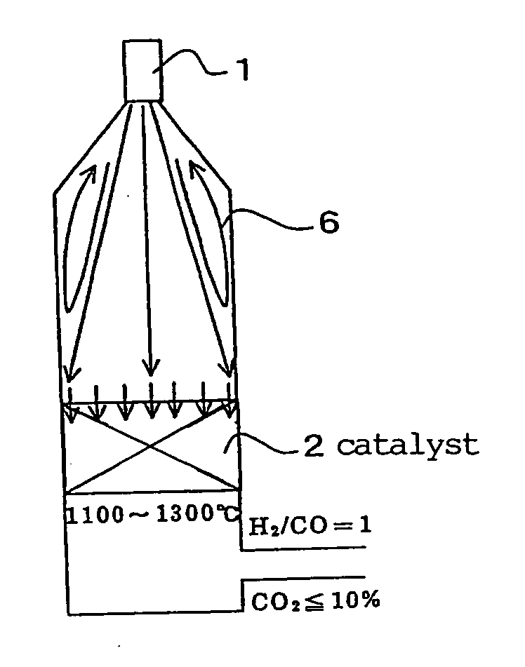
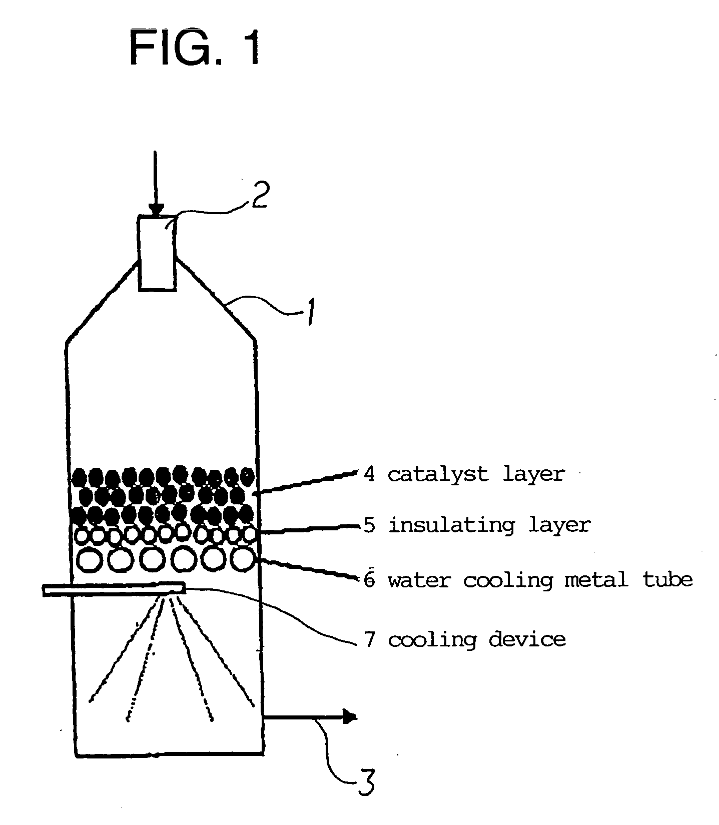
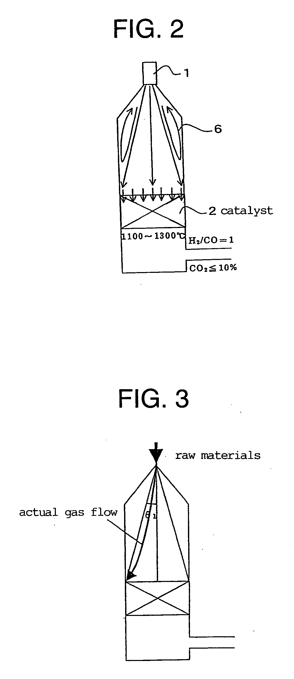
[0025] If the temperature for reaching an equilibrium state (the outlet temperature of the catalyst layer) is set to 1100 to 1300° C., although the ratio of hydrogen to carbon monoxide is reduced, soot is not produced, and the amount of carbon dioxide as an auxiliary raw material can be also reduced. As a result, using an LNG fuel, it is possible to reduced the carbon dioxide concentration in the produced gas to 10 vol % or less. Using an LPG fuel, it is possible to make the carbon dioxide concentration in the produced gas to 5 vol %. Also, since a catalyst is operated efficiently at high temperatures, a high price catalyst containing noble metals is not required, and the amount of the catalyst may be decreased.

Problems solved by technology

However, it was found that the medium oil disclosed in the above document was decomposed, volatilized and, thus decreased in the amount slowly over time.

Method used


Image

  • Method for preparing synthesis gas, method for preparing dimethyl ether using synthesis gas, and furnace for preparing synthesis gas
  • Method for preparing synthesis gas, method for preparing dimethyl ether using synthesis gas, and furnace for preparing synthesis gas
  • Method for preparing synthesis gas, method for preparing dimethyl ether using synthesis gas, and furnace for preparing synthesis gas

Examples


example

[0243] A produced synthesis gas, or a purge gas of a DME synthesis reaction system was mixed with a raw material and introduced. The condition for this embodiment was such as to prepare a synthesis gas having the H2 / CO ratio of 0.8 to 1.2. Under such condition, since the amount of the introduced steam was small, the gas excluding the condensed water was introduced. The outlet temperature of a catalyst layer was set at 1100 to 1300° C., and the synthesis gas was rapidly cooled to 600° C. or less in the lower part of the catalyst layer.

[0244] In Table 2, Comparative Examples 1 and 2 show examples of not circulating the synthesis gas, and Examples 1 and 2 show examples of circulating the synthesis gas.

[0245] It was found that in Examples 1 and 2, the amount of the introduced CO2 in the raw gas could be lowered, and also the amount of CO2 in the produced gas was decreased to 8 dry vol %. Since it is not easy to reduce the amount of CO2 in a produced gas by even 1 dry vol %, the signif...

example 1

[0390] {Purification of the Medium Oil of the Present Invention}

[0391] By conducting polymerization of 1-decene as a raw material in the presence of an aluminum chloride catalyst and water as an a promoter at −20 to 30° C. and saturation with addition of hydrogen then purification, obtained was a product, that is, the medium oil. Physical properties thereof were adjusted depending on the composition of the raw material, the polymerization temperature and / or conditions for the purification (that is, distillation). The obtained medium oil was subjected to determination of chemical properties by the following means.

[0392] In particular, the weight average molecular weight of the medium oil was measured by means of mass spectroscopy and gel-permeation chromatography. The vapor pressure was determined using a boiling point procedure by means of an ebulliometer. % Cp as a percentage of paraffinic carbon atoms to the total carbon atoms was determined by the n-d-M method (ASTM D 3238). The...

example 2

[0397] {Synthesis of Dimethyl Ether / Methanol and Evaluation of Synthesis Efficiency}

[0398]FIG. 14 shows a constructional scheme of a synthesis apparatus illustrating the synthesis of dimethyl ether.

[0399] In a reactor of the synthesis apparatus, added were 1552 g of the medium oil of Example 1, then 259 g of a methanol synthesis catalyst based on copper-zinc-alumina (CuO / ZnO / Al2O3:31 / 16 / 53) and 129 g of an alumina based methanol dehydration / shift catalyst (CuO / SiO2.Al2O3) to form a slurry-bed [weight ratio of the methanol synthesis catalyst and the methanol dehydration / shift catalyst (methanol synthesis catalyst:methanol dehydration / shift catalyst)=2:1, and the total weight of the methanol synthesis catalyst and the methanol dehydration / shift catalyst being 388 g], a slurry was prepared by mixing the above and then the reactor was closed. By passing the raw gas material [carbon monoxide: 18.11 NL / min, hydrogen gas: 18.11 NL / min, the amount to be passed was determined using a mass f...


PUM

PropertyMeasurementUnit
temperatureaaaaaaaaaa
retention timeaaaaaaaaaa
gas retention timeaaaaaaaaaa

Abstract

Disclosed is a process for producing a synthesis gas containing no hydrocarbon and reduced concentration of carbon dioxide among the produced synthesis gas. The process according to the present invention comprises reforming the gas generated by partial combustion of hydrocarbon using a catalyst in a furnace for generating the synthesis gas mounted on a catalyst layer inside the furnace, and producing the synthesis gas comprising hydrogen and carbon monoxide as a main components, and is characterized in that the temperature at outlet of the catalyst layer ranges from 1100 to 1300° C. and the concentration of carbon dioxide in the produced synthesis gas is not more than 10% by volume.

Description

TECHNICAL FIELD [0001] The present invention relates to a method for preparing a synthesis gas containing hydrogen and carbon monoxide as main components, by reforming a gas produced by a partial combustion of a hydrocarbon with a catalyst, and to a method for preparing dimethyl ether using the synthesis gas, in which the synthesis gas is the most suitable one as a synthesis gas of H2 / CO=0.8 to 1.2 (molar ratio) BACKGROUND ART [0002] A synthesis gas containing hydrogen and carbon monoxide is used as a raw material for the synthesis of F-T, methanol, ammonia, or the like. [0003] The synthesis gas is prepared from various organic compounds. It is known that a method for preparing the synthesis gas is a reaction of the organic compound with steam and / or carbon dioxide, a partial oxidation of the organic compound by oxygen and / or air, etc. [0004] In particular, with regard to a gaseous organic compound, the following methods are used: (1) a method of reacting an organic compound with st...

Claims


Application Information

Patent Timeline
Patent Type & Authority Applications(United States)
IPC IPC(8): C01B3/24C01B3/02C01B3/38C07C41/09
CPCC01B3/386C01B2203/0261C01B2203/06C07C41/09C07C29/16C07C43/043C01B3/38C07C41/00C07C43/04
Inventor OKUYAMA, KEIICHIOGAWA, TAKASHIAOKI, SEIJISHIKADA, TSUTOMUSUZUKI, TOSHIFUMIMIYOSHI, YASUOKONAYASHI, NOBUAKISUZUKI, KAZUNO
Owner INPEX CORP
Learn More