Polarization analyzer

a polarization analyzer and analyzer technology, applied in the direction of optical radiation measurement, instruments, polarising elements, etc., can solve the problems of reducing the area of one device, reducing the number of devices to be pasted, and reducing the number of devices. , to achieve the effect of good chemical, thermal and mechanical stability, easy formation of a film, and high refractive index

Inactive Publication Date: 2006-06-15
AUTOCLONING TECH
View PDF1 Cites 40 Cited by
  • Summary
  • Abstract
  • Description
  • Claims
  • Application Information

AI Technical Summary

Benefits of technology

[0013] A polarizer or a waveplate consisting of the photonic crystal has an operation wavelength band which can be freely set by controlling the refractive index, a filling rate, a period Lx of the groove line, and a period L2 in the laminating direction of the material constituting the device. As a low refractive index medium, a material containing SiO2 as a main component is most usually used. The material has a wide transparent wavelength band and good chemical, thermal, and mechanical stabilities, and can easily forms a film. However, other optical glass may also be used, and a material such as MgF2 having a low refractive index may be used. As a high refractive index material, a semiconductor such as Si or Ge or an oxide or a nitride such as Ta2O5, TiO2, Nb2O5, HfO, or Si3N4 can also be used. The oxide or the nitride has a wide transparent wavelength range, and can also be used in a visible light region. On the other hand, although the semiconductor is used in only an near-infrared region, the semiconductor has a high refractive index advan...

Problems solved by technology

This is because, on a manufacturing process, a device except for a device having a size of millimeters or more or centimeters or more cannot be manufactured since an anisotropic singlecrystalline material is polished or a film or glass is drawn in one direction.
However, a reduction in area of one device and a reduction in number of devices to be pasted are limited.
In addition, it is difficult to accurately align the axes of small chips.
However, since the depth of a groove di...

Method used


Image

  • Polarization analyzer
  • Polarization analyzer
  • Polarization analyzer

Examples


Embodiment Construction

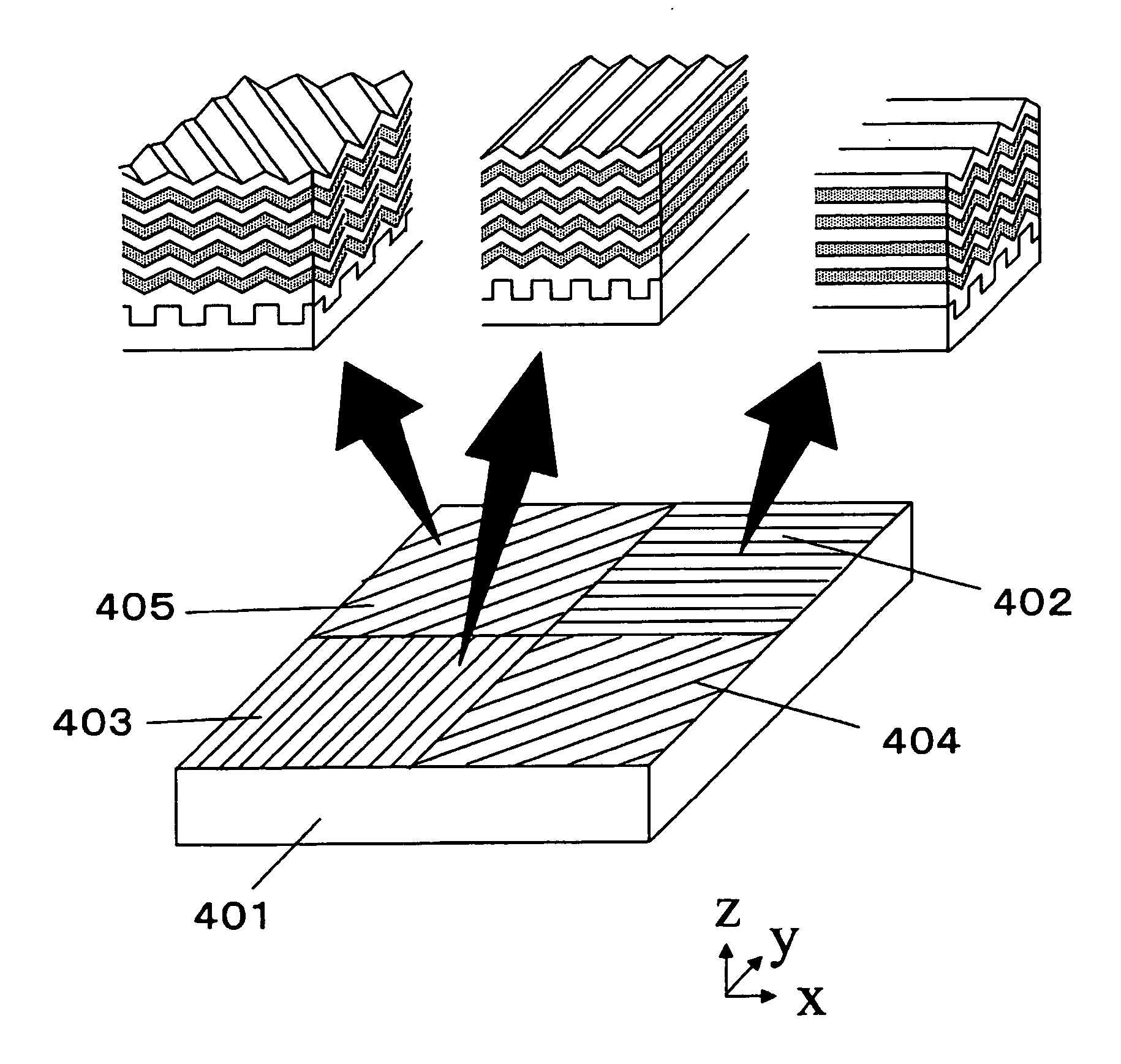
[0037] A polarization analyzer composed of a small polarizer array consisting of autocloning type photonic crystal and having different optical-axis directions and a light-receiving device array or a polarization analyzer obtained by adding a quarter waveplate to the former polarization analyzer will be described below. The polarization analyzer can be used when polarization of signal light in optical communication, or the polarization analyzer can be used in various optical sensors.

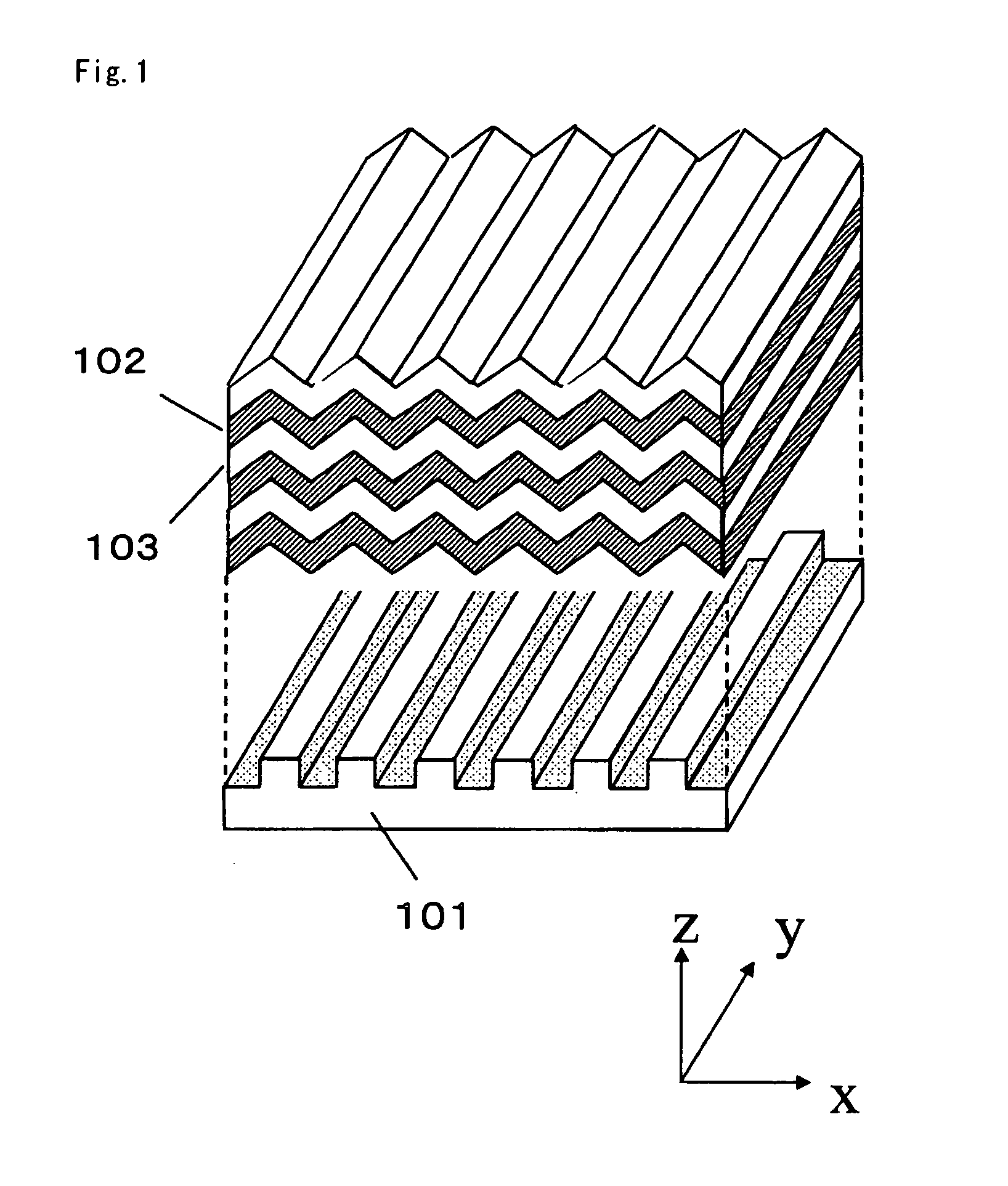
[0038] At first, a polarizer array 401 shown in FIG. 4 will be described. A polarizer has a structure shown in FIG. 1, and is composed of an alternative multilayer film consisting of Si and SiO2. Four divided regions are formed on an x-y plane. Each film has an uneven shape in each region. The films are periodically repeated in one direction on the x-y plane determined in each region. The direction of the grooves in a first region 402 is set at 0° to the x axis. The direction of the grooves in a second ...


PUM


Abstract

A thin polarizer array and a wavelength plate array that are composed of micro regions having different optical axis directions and wavelength characteristics and have a high extinction ratio and a low insertion loss, and a polarization analyzer using them are disclosed. An array of micro periodic grooves is formed on a substrate, with the directions changed from one region to another. An alternating multilayer film formed by alternating a layer of high refractive index material such as Si or Ta2O5 and a layer of low refractive index material such as SiO2 is formed by bias sputtering. By selecting a condition that each layer maintains its periodic projecting/recessed shape, an array of photonic crystal polarizer is formed. By mounting this array of photonic crystal polarizer in a photodetector array, a polarization analyzer that is small, has no movable part, is composed of a small number of components, and enables high-precision measurement is constituted.

Description

TECHNICAL FIELD [0001] The present invention relates to a polarization analyzer composed of a plurality of small regions and using an array of polarizers and waveplates having different optical axis directions. BACKGROUND ART [0002] A polarizer, which is one of polarized light control devices, is a device to transmit only a vibration component in a specific direction of unpolarized light or elliptically polarized light in which an electromagnetic field vibrates in unspecific directions to obtain linearly polarized light. The polarizer is one of the most basic optical devices. The device is commonly used in an optical communication device, an optical pickup for an optical disk, a liquid crystal display, an optical application measurement, and the like. Polarizers are roughly classified into two groups by the operation type; 1 st grope directs to a polarizer which absorbs an unnecessary polarized wave and, 2nd grope directs to a polarizer which divides two orthogonal polarized wave co...

Claims


Application Information

Patent Timeline
IPC IPC(8): G01J4/00G02B5/30G02B27/28
CPCG02B27/288G02B5/3033G02B5/3041
Inventor KAWAKAMI, SHOJIROSATO, TAKASHIKAWASHIMA, TAKAYUKIISHIKAWA, WATARU
Owner AUTOCLONING TECH
Why Eureka
Try Eureka