Means for removing unwanted ions from an ion transport system and mass spectrometer

a technology of ion transport system and mass spectrometer, which is applied in the direction of mass spectrometer, particle separator tube, isotope separation, etc., can solve the problems of affecting the detection of some elements, affecting the operation of instruments, and attenuating the ion beam, so as to reduce the unresolved baseline noise signal, facilitate access, and facilitate replacement or re-usability

Inactive Publication Date: 2006-07-13
THERMO FISHER SCI BREMEN
View PDF24 Cites 11 Cited by
  • Summary
  • Abstract
  • Description
  • Claims
  • Application Information

AI Technical Summary

Benefits of technology

[0031] Preferably the second axis of the mass to charge ratio analysing means is offset from the first axis. This is effective in reducing the unresolved baseline noise signal that is generally present in ICPMS instruments.
[0032] Preferably, the first evacuated chamber is divided into a first region adjacent to the expansion chamber, and a second region adjacent to the collision cell, by a large diameter aperture. The ion optical device is located in the second region, and the first region may contain an extractor lens driven at a negative potential. Preferably the diameter of the aperture is approximately 20 mm, and it is preferably sealable. This may be achieved by means of a flat plate on an O-ring seal. This enables the second region to be isolated and maintained at a high pressure while the expansion chamber and the first region are vented to atmospheric pressure. This facilitates access to the components most prone to contamination, so that they can be readily replaced or refurbished.

Problems solved by technology

A problem common to all of these, although most troublesome in low-resolution devices such as quadrupoles, is the presence in the mass spectrum of unwanted artefact ions that impair the detection of some elements.
If the collision cell contains a significant partial pressure of argon, this will upset the operation of the instrument in two ways.
Firstly, the ion beam will be attenuated by collisions between the ions in the beam and argon neutrals.

Method used


Image

  • Means for removing unwanted ions from an ion transport system and mass spectrometer
  • Means for removing unwanted ions from an ion transport system and mass spectrometer
  • Means for removing unwanted ions from an ion transport system and mass spectrometer

Examples


Embodiment Construction

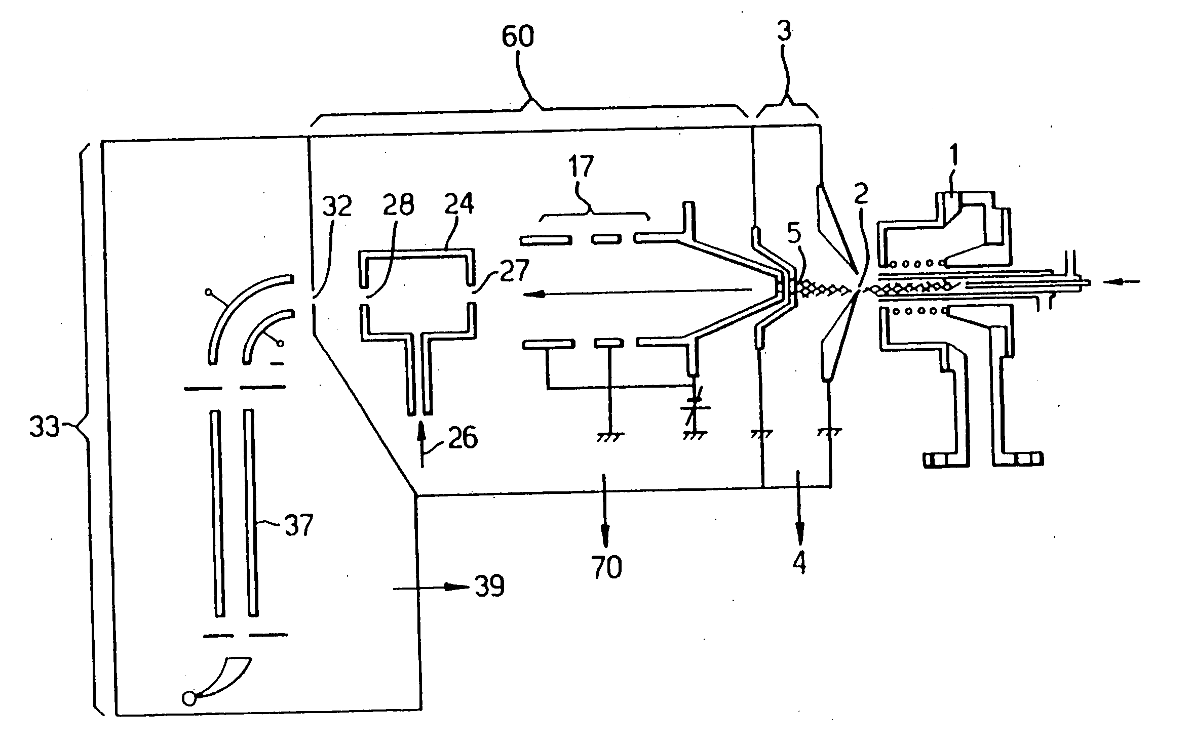
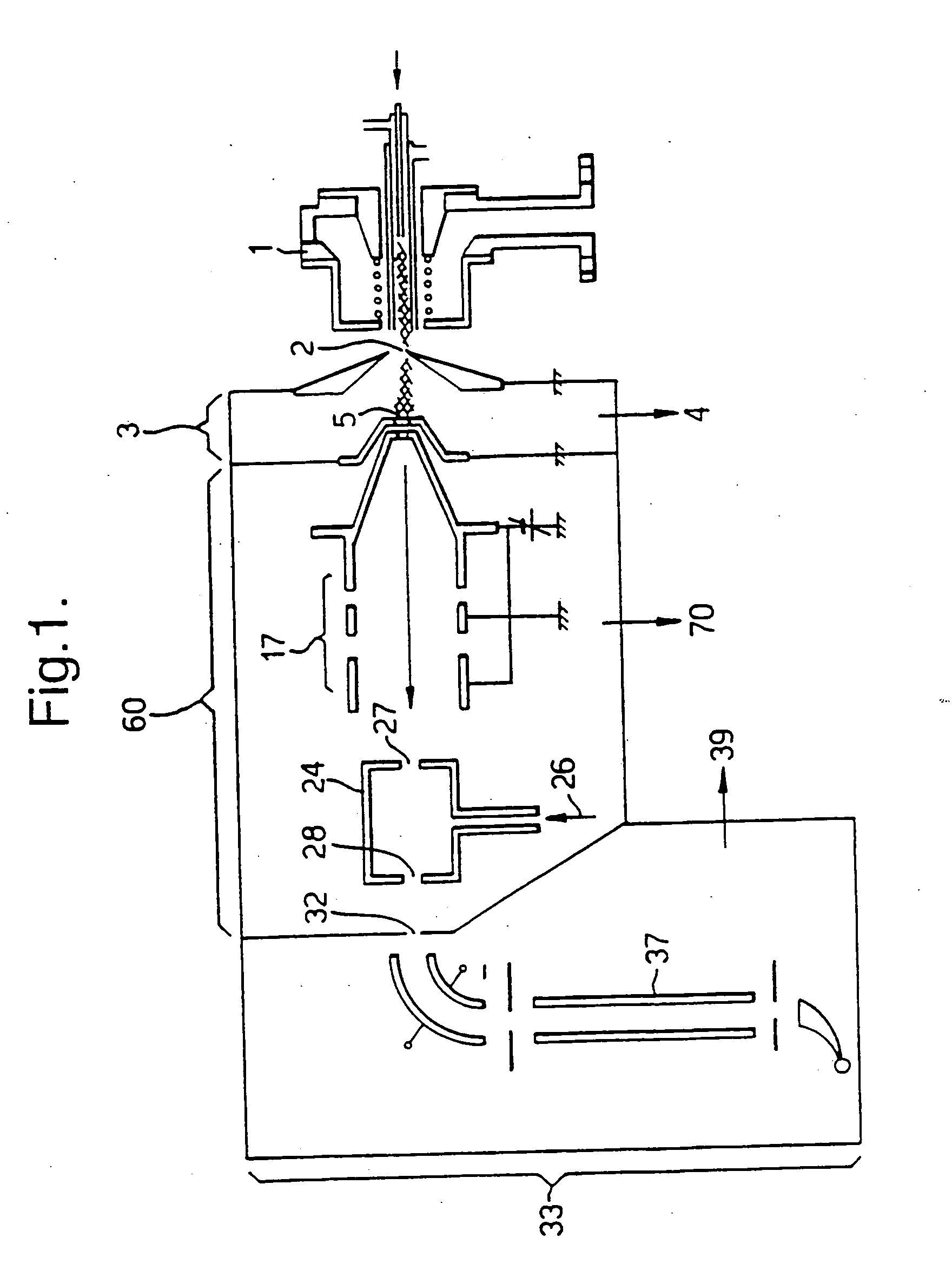
[0036] In the prior art mass spectrometer of FIG. 1, the inductively-coupled plasma (ICP) ion source 1 is of conventional design, operating at atmospheric pressure. Ions are generated in the plasma and entrained in the general gas flow, part of which passes through a sampling aperture 2. The expansion chamber 3, is located behind the sampling aperture 2 and is evacuated by means of a rotary-vane vacuum pump at 4. The gas flow that passes through the first aperture 2 expands as a super-sonic free jet, the central portion of which passes through the second aperture 5 into an evacuated chamber 60. Aperture 5 is in the form of a skimmer, for example such as described in U.S. Pat. No. 5,051,584. Located in the evacuated chamber 60 is an ion optical device 17, in this case a lens stack, and a collision cell 24 having an entrance aperture 27 and an exit aperture 28. The collision cell 24 is a simple passive collision cell ie a chamber pressurised with target gas 26. On exiting the collisio...


PUM

PropertyMeasurementUnit
temperaturesaaaaaaaaaa
partial pressureaaaaaaaaaa
stagnation pressureaaaaaaaaaa

Abstract

The present invention relates to inductively coupled plasma mass spectrometry (ICPMS) in which a collision cell is employed to selectively remove unwanted artefact ions from an ion beam by causing them to interact with a reagent gas. The present invention provides a first evacuated chamber (6) at high vacuum located between an expansion chamber (3) and a second evacuated chamber (20) containing the collision cell (24). The first evacuated chamber (6) includes a first ion optical device (17). The collision cell (24) contains a second ion optical device (25). The provision of the first evacuated chamber (6) reduces the gas load on the collision cell (24), by minimising the residual pressure within the collision cell (24) that is attributable to the gas load from the plasma source (1). This serves to minimise the formation, or re-formation, of unwanted artefact ions in the collision cell (24).

Description

FIELD OF THE INVENTION [0001] The present invention relates to inductively coupled plasma mass spectrometry (ICPMS). However, the concepts can be applied to any type of mass spectrometer which generates unwanted artefact ions as well as ions of analytical significance, such artefact ions having properties that allow them to be selectively removed from the ion beam by causing them to interact with a reagent gas whilst the ions of analytical significance are substantially retained in the beam. BACKGROUND OF THE INVENTION [0002] The general principles of ICPMS are well known. It is a method of elemental analysis providing information about the elemental composition of a sample, with little or no information about its molecular structure. Typically, the sample is a liquid, which is nebulised and then passed through an electrically-maintained plasma, in which the temperature is high enough to cause atomization and ionisation of the sample. Typically temperatures greater than 5000 K are u...

Claims


Application Information

Patent Timeline
Patent Type & Authority Applications(United States)
IPC IPC(8): H01J49/00H01J49/06G01N27/62H01J49/10H01J49/42
CPCH01J49/0045H01J49/04H01J49/22H01J49/421H01J49/105
Inventor MARRIOTT, PHILIP
Owner THERMO FISHER SCI BREMEN
Why Eureka
Try Eureka