System and method for servo control of nonlinear electromagnetic actuators

a nonlinear electromagnetic actuator and servo control technology, applied in electrical control, non-mechanical valves, magnetic bodies, etc., can solve the problems of failure mode of print wire solenoids, insufficient basis for a servo system generating large mechanical motions and correspondingly large changes, and eliminate closure impact and associated noise, the effect of reducing the number of servos

Inactive Publication Date: 2006-08-03
SEALE JOSEPH B +1
View PDF2 Cites 89 Cited by
  • Summary
  • Abstract
  • Description
  • Claims
  • Application Information

AI Technical Summary

Benefits of technology

[0013] An object of the invention is control of the powered closure of a solenoid to eliminate closure impact and associated noise, efficiency loss, and progressive damage, including damage to the properties of the magnetic materials. Related objects are to eliminate closure impact through two strategies: a low-cost strategy called “launch control;” and a feedback strategy called “servo control.” A further object is to employ servo control for dynamically maintaining a solenoid position in a hovering or levitating mode. A still further object is to employ servo control for smooth opening of a solenoid.
[0015] Within mechanical “servo control,” common terminology describes a sense parameter; indicating mechanical response of a servo system; a target parameter to be subtracted from the sense parameter and resulting in an error parameter; PID gain parameters describing three aspects of feedback amplification of the error parameter, namely: Proportional feedback; Integral feedback; and Derivative feedback; and a drive parameter arising from the summation of the P, I, and D feedback components and that determines the actuation output causing the controlled mechanical response. A servo control loop is characterized by a settling time constant, which may be defined by the shortest time interval beyond which an error parameter continues to be reduced by at least a specified ratio below an initial error defined at the start of the time interval. The settling time constant is generally minimized by an optimum combination of proportional and derivative feedback trains. Increasing of the integral feedback gain generally improves long term error reduction while increasing the settling time constant, thus degrading short term settling and, for excessive integral feedback gain, causing instability and oscillation of the servo system.
[0019] In the context of related drive parameters, sense parameters, and target parameters for servo control, an object is to split a solenoid control servo system functionally into coupled inner and outer loops with distinct drive, sense, and target parameters, and such that the inner loop has a substantially shorter settling time constant than the outer loop. A related object is to establish an outer control loop for which the sense parameter is a measure of position and the drive parameter is a signal related to force. The sensed measure of position may be a solenoid current, or a measured AC variation in a solenoid current slope, or an auxiliary measurement of mechanical position, e.g., via a Hall effect sensor and permanent magnet or an optical sensor and a light source. A further related object is to establish an inner control loop for which the sense parameter is a measure of variation in magnetic flux, and for which the drive parameter of the outer loop defines at least an additive component of the target parameter being compared with the sensed measure of magnetic flux, and for which the drive parameter is a coil-drive voltage. Note that this drive voltage is the actuation output ultimately controlling mechanical motion in the solenoid. A still further related object is to establish an efficient voltage switching oscillation in an amplifier driving a solenoid coil, and to cause the duty cycle of that switching oscillation to vary such that the short-term-average voltage driving the coil is the voltage drive parameter of the inner loop. As a way of simplifying the electronic design of the servo system, an object related to the establishment of a switching oscillation with a controlled duty cycle is to design a controller loop with an intentional short-term instability that gives rise to switching oscillations having the desired characteristics.
[0027] In an application of the invention to magnetic levitation and propulsion of a monorail car, an object is to control multiple magnetic lifting modules in a common mode for regulating height of levitation, in a differential mode for regulating tilt, and in a variable-gain traveling wave mode for generating thrust through engagement of traveling magnetic waves with periodic ripples in a track. A related object for minimizing hysteresis and eddy current losses in a track is to generate lifting forces of magnetic attraction from magnetic fields directed mostly vertically and laterally relative to a longitudinal direction of in motion, thereby generating magnetic flux in the track that remains relatively constant during the period of passage of a levitating car. A related object for minimizing lifting power is to combine permanent and soft magnetic materials for generating lift with a reduced or zero-average current to electromagnetic lifting modules. SUMMARY OF THE INVENTION

Problems solved by technology

Magnetic steel solenoid parts are typically solid rather than laminated, because eddy current losses in dynamic operation are not a design consideration.
The result is to cause the solenoid to stick in its closed position after external current is removed.
This is a failure mode for print wire solenoids.
While these relationships are needed building blocks in the conception of the instant invention, they are not an adequate basis for a servo system generating large mechanical motions and correspondingly large changes in solenoid inductance.
First, there are limitations to the linearized small-perturbation models taught by Jayawant et al for controlling large solenoid motions.
Second, dynamic stability problems would remain even with a more complicated and costly servo implementation using non-linear circuit models, e.g., computing position as the ratio of current / flux and force as the square of flux, instead of Jayawant's tangential linear approximations of the ratio and square law relations.
It is understood that servo control over a third order system is prone to instability since phase shifts around the control loop, tending toward 270 degrees at high frequencies, readily exceed 180 degrees over the bandwidth for which control is desired.
A combination of high efficiency and tight control spell problems for loop stability, for even with single-pole phase lead compensation, minor resonances, e.g., from mechanical flexure, can throw the servo system into oscillation.
The mixed actuation voltage was usually well in excess of the minimum requirement, and the result was actuation with excessive force and resulting severe contact bounce.
When a solenoid begins to close, the resulting “back EMF” due to armature motion tends to reduce electric current, in relation to gap, to maintain a constant magnetic flux, with the result that increases in force with gap closure are only moderate.
Even under conditions where sufficiently soft landing is achieved, it is at the cost of a substantial excess energy consumption to generate a long ramp of pulse duty cycle and current, only the middle portion of which causes actuation.
Though such a system responds to some of the limitations of Wieloch, it is not readily adaptable to an actuation system that must respond to changing conditions of starting position and the load force curve while achieving quiet, impact-free, efficient operation.
Magnetic characteristics in this region have presumably been considered too nonlinear for practical control.
In particular, the region of operation approaching full closure and contact of mating magnetic surfaces presents a very steeply changing inductance and correspondingly steep change in the sensitivity of force to change in coil current.
Yet problems with stability and non-linearity inherent to magnetically soft ferromagnetic-core solenoids have impeded the development of servo solenoids, and therefore have prevented the potential efficiency advantages just described.

Method used


Image

  • System and method for servo control of nonlinear electromagnetic actuators
  • System and method for servo control of nonlinear electromagnetic actuators
  • System and method for servo control of nonlinear electromagnetic actuators

Examples


Embodiment Construction

Launch Control Methods

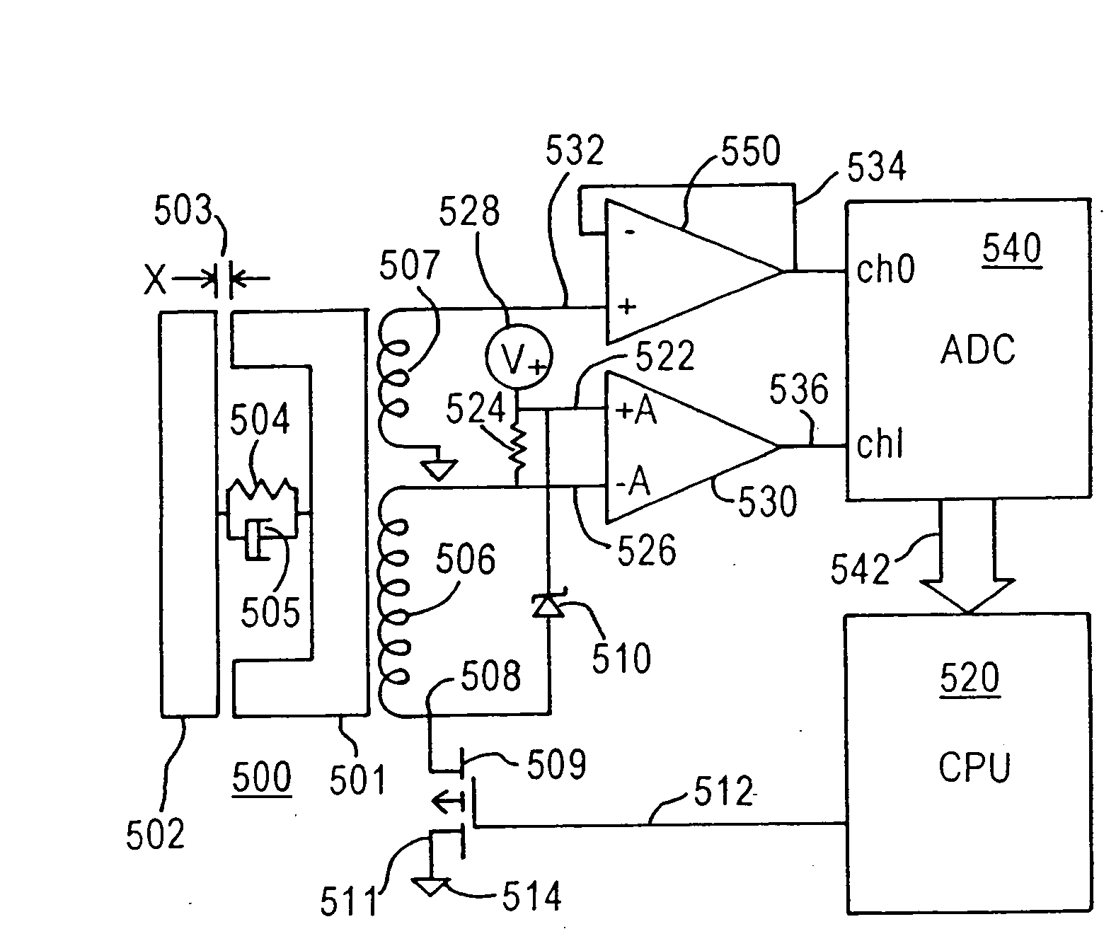
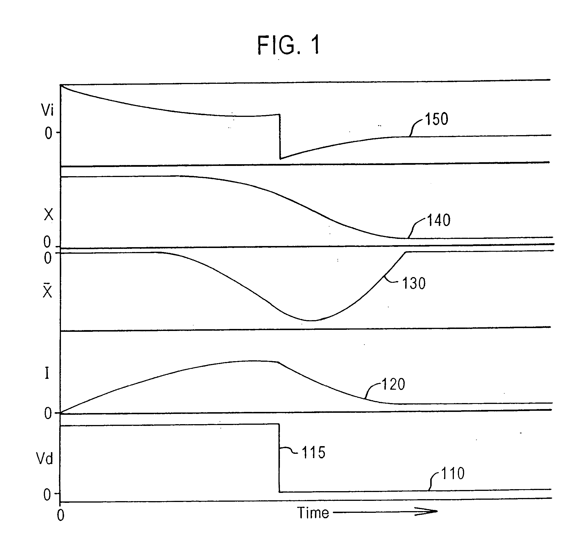
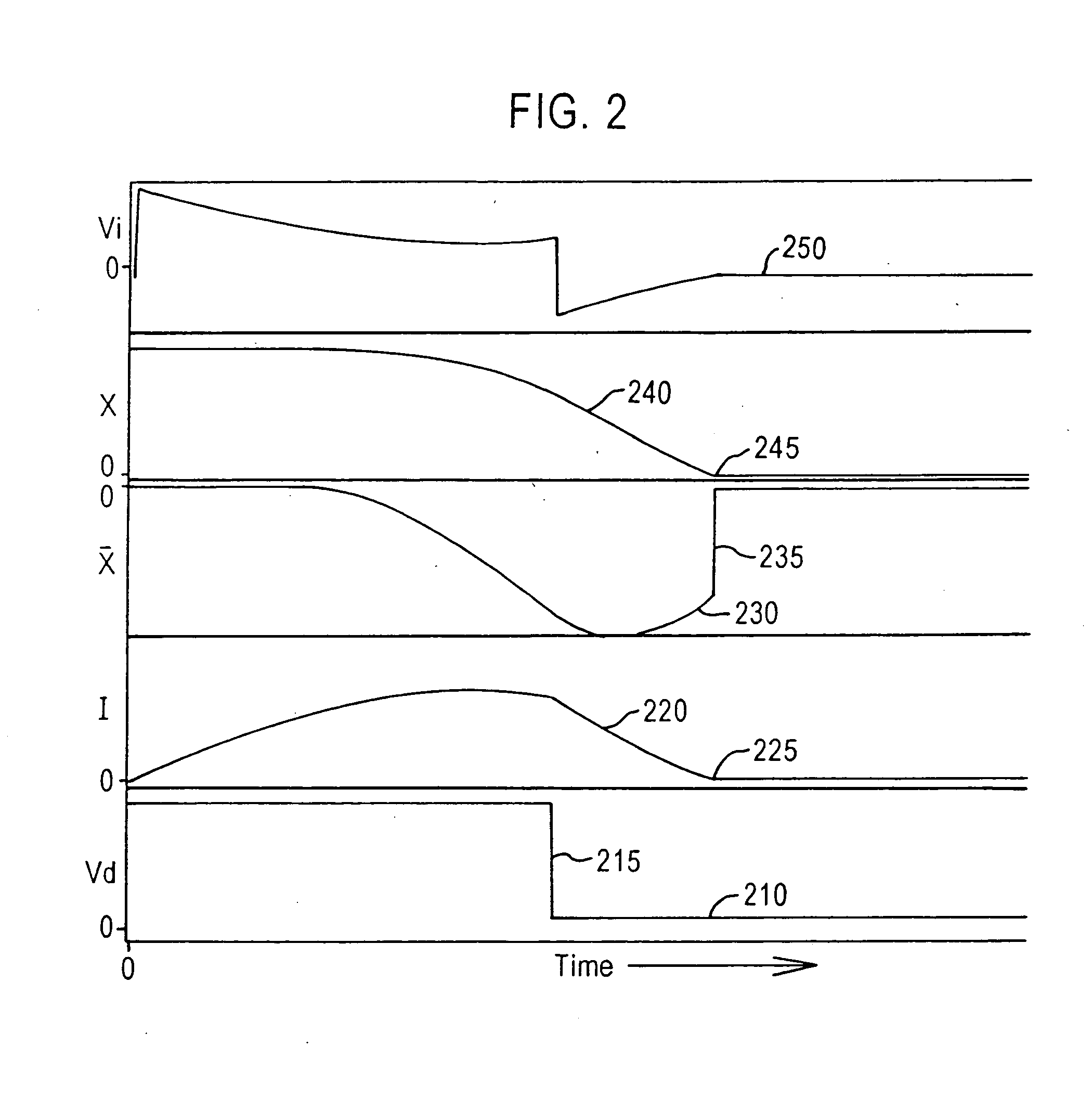
[0152] We have discussed the achievement of linear servo control, whose outcome is to establish a roughly exponential decay of error, including simple exponential decay and ringing within a decaying exponential envelope. A real solenoid controller has built in slew rate limits that set boundaries to the region of linear behavior and, consequently, the range of applicability of linear control methods. Typically, the solenoid driver amplifier operates between voltage output limits that set the maximum rate at which solenoid current can be increased and decreased. In the most common two-state output controller, the “on” output state drives current toward a maximum while the “off” output state short-circuits the solenoid winding through a transistor, allowing the current to vary and, ultimately, decay, in passive response to resistance and changing magnetic gap. The momentum attained by the solenoid shuttle falls into two categories: mechanical and electromagnetic...


PUM

PropertyMeasurementUnit
diameteraaaaaaaaaa
pressureaaaaaaaaaa
pressureaaaaaaaaaa

Abstract

Servo control using ferromagnetic core material and electrical windings is based on monitoring of winding currents and voltages and inference of magnetic flux, a force indication; and magnetic gap, a position indication. Third order nonlinear servo control is split into nested control loops: a fast nonlinear first-order inner loop causing flux to track a target by varying a voltage output; and a slower almost linear second-order outer loop causing magnetic gap to track a target by controlling the flux target of the inner loop. The inner loop uses efficient switching regulation, preferably based on controlled feedback instabilities, to control voltage output. The outer loop achieves damping and accurate convergence using proportional, time-integral, and time-derivative gain terms. The time-integral feedback may be based on measured and target solenoid drive currents, adjusting the magnetic gap for force balance at the target current. Incorporation of permanent magnet material permits the target current to be zero, achieving levitation with low power, including for a monorail deriving propulsion from the levitation magnets. Linear magnetic approximations lead to the simplest controller, but nonlinear analog computation in the log domain yields a better controller with relatively few parts. When servo-controlled solenoids provide actuation of a pump piston and valves, electronic LC resonance measurements determine liquid volume and gas bubble volume.

Description

CROSS-REFERENCE TO RELATED APPLICATIONS [0001] The present application is a continuation of commonly assigned copending U.S. patent application Ser. No. 09 / 771,892, which was filed on Jan. 30, 2001, by Joseph B. Seale et al., for a SYSTEM AND METHOD FOR SERVO CONTROL OF NONLINEAR ELECTROMAGNETIC ACTUATORS, which is a divisional application of U.S. patent application Ser. No. 08 / 882,945, which was filed on Jun. 26, 1997, by Joseph B. Seale et al., for a SYSTEM AND METHOD FOR SERVO CONTROL OF NONLINEAR ELECTROMAGNETIC ACTUATORS now U.S. Pat. No. 6,208,497, which was issued on Mar. 27, 2001, and each of which is hereby expressly incorporated by reference.BACKGROUND OF THE INVENTION [0002] 1. Field of the Invention [0003] The present invention relates to systems and methods for controlling the movement of mechanical devices. More particularly, the present invention relates to the servo control of electromagnetic devices. Still more particularly, the present invention relates to the serv...

Claims


Application Information

Patent Timeline
Patent Type & Authority Applications(United States)
IPC IPC(8): H01H47/00B60L13/06B60L13/10F01L9/20F02D13/02F02D41/14F02D41/20H01F7/16H01F7/18H02K41/03H02N15/00H02P25/02H02P25/06
CPCF01L9/04F01L2009/0405F01L2009/0486F02D13/0253F02D41/1401F02D41/20F02D2041/001F02D2041/1419F02D2041/2027F02D2041/2055F02D2041/2058F02D2041/2079H01F7/1607H01F7/18H01F7/1844H01F2007/185H01F2007/1866H01F2007/1894H01H47/325H02K41/03H02N15/00H02P25/027Y02T10/18H02P25/032B60L13/06Y02T10/12F01L2009/2105F01L2009/4086F01L9/20H01H47/32
Inventor SEALE, JOSEPH B.BERGSTROM, GARY E.
Owner SEALE JOSEPH B
Why Eureka
Try Eureka