Flexible reticulated foam fluid treatment media and method of preparation

Inactive Publication Date: 2006-08-17
FLUID TREATMENT SYST
View PDF10 Cites 21 Cited by
  • Summary
  • Abstract
  • Description
  • Claims
  • Application Information

AI Technical Summary

Benefits of technology

[0022] During the compression steps, the coated reticulated foam substrate is optimally compressed by passing through the gap between two rollers where the thickness of the gap between the rollers when the substrate is coated is correlated to the amount of compression force applied to the coated substrate. The gap is set by a device that applies tension to the rollers so that the hill surface of one roller meshes with a valley surface of the adjacent roller to assist in feeding the coated substrate through the rollers. Adjusting the te

Problems solved by technology

Polluted air and contaminated exhaust from combustion processes and effluent from chemical production can be harmful and must be treated to remove contaminants prior to release into the environment.
When used to purify water in swimming pools, spas and hot tubs chlorinated and brominated compounds are dangerous to the environment and can cause human health problems, including asthma in children and birth defects in pregnant women.
Because the metal particles are reactive, particles within the packed beds fuse together in the presence of the fluid or decompose to form fines that clog the bed and reduce porosity, resulting in a reduction of treatment efficiency and excessively high pressure drops through the bed or column of particles.
Although rigid metal reticulated foam media is durable and sta

Method used


Image

  • Flexible reticulated foam fluid treatment media and method of preparation
  • Flexible reticulated foam fluid treatment media and method of preparation
  • Flexible reticulated foam fluid treatment media and method of preparation

Examples


example i

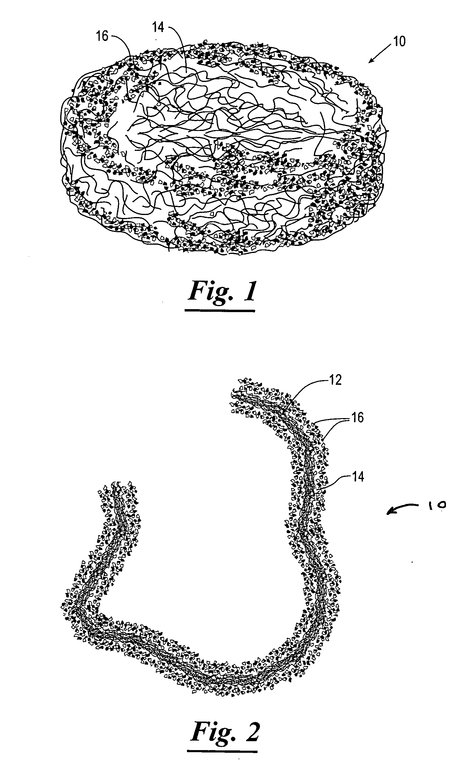
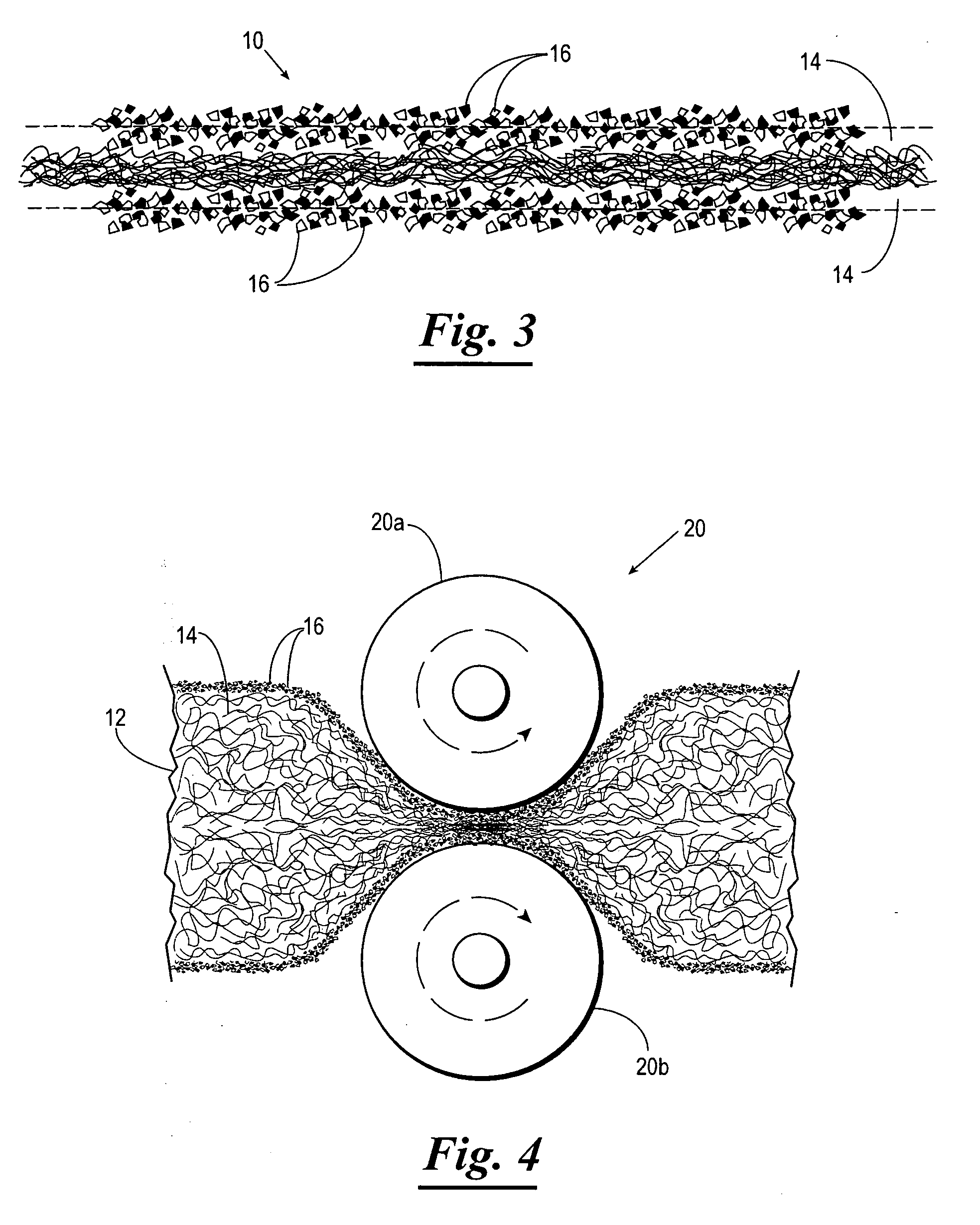
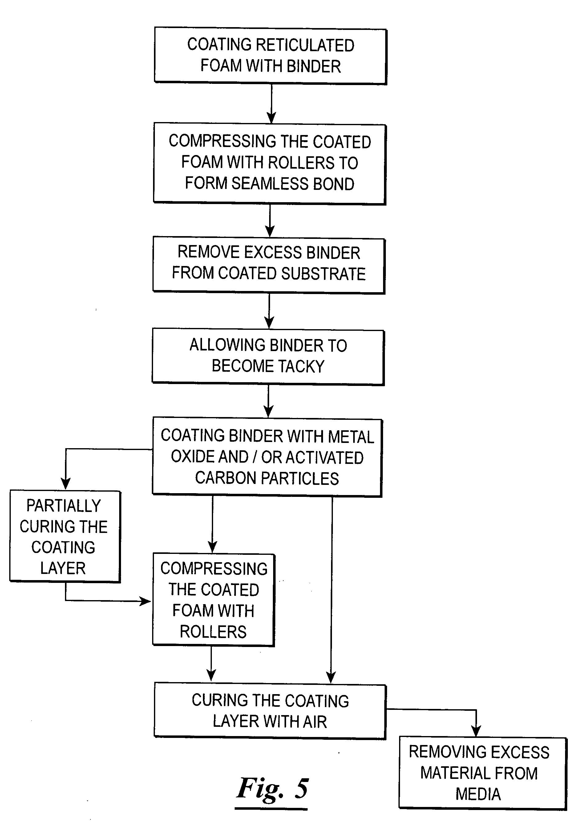
[0045] A polyethylene reticulated foam substrate with a density of around 10 pores per square inch, a thickness of approximately one inch and a diameter of around six inches is submerged into a liquid polychloroprene binder for sufficient time to coat the polyethylene substrate with an excess amount of the binder. The coated substrate is passed through the two rollers of the wringer apparatus to eliminate air pockets and create a tight bond between the binder layer and the substrate. The tension applied to the rollers of the wringer apparatus was set to maintain a gap of around 0.15 inches between the rollers during compression of the one-inch thick media. Excess binder is removed from the void spaces of the reticulated foam during compression of the foam in the wringer apparatus. The substrate coated with the binder is allowed to become tacky before application of the particulate materials to the binder. 200 mesh powder consisting of copper / zinc metal particles is applied to the co...

example ii

[0046] A polyethylene reticulated foam substrate with a density of around 10 pores per square inch, a thickness of around one inch and a diameter of eight inches is submerged into a liquid polychloroprene binder for sufficient time to coat the polyethylene substrate with an excess amount of the binder. The coated substrate is passed through the two rollers of the wringer apparatus to eliminate air pockets and create a tight bond between the binder layer and the substrate. The tension applied to the rollers of the wringer apparatus was set to maintain a gap of around 0.15 inches between the rollers during compression of the one-inch thick media. Excess binder is removed from the void spaces of the reticulated foam during compression of the foam in the wringer apparatus. The substrate coated with the binder is allowed to become tacky before application of the particulate materials to the binder. 200 mesh powder consisting of copper / zinc metal particles is applied to the coated substra...

example iii

[0047] A polyethylene reticulated foam substrate with a density of around 15 pores per square inch, a thickness of one inch and a diameter of around three inches is submerged into a liquid polyurethane binder for sufficient time to coat the polyethylene substrate with an excess amount of the binder. The coated substrate is passed through the two rollers of the wringer apparatus to eliminate air pockets and create a tight bond between the binder layer and the substrate. The tension applied to the rollers of the wringer apparatus was set to maintain a gap of around 0.2 inches between the rollers during compression of the one-inch thick media. Excess binder is removed from the void spaces of the reticulated foam during compression of the foam in the wringer apparatus. The substrate coated with the binder is allowed to become tacky before application of the particulate materials to the binder. 200 mesh powder consisting of KDF-55 metal particles is applied to the coated substrate and kn...


PUM

PropertyMeasurementUnit
Lengthaaaaaaaaaa
Lengthaaaaaaaaaa
Pore sizeaaaaaaaaaa

Abstract

Flexible reticulated foam fluid treatment media and a method of making same. The flexible fluid treatment media includes a flexible reticulated foam substrate, a binder coating the flexible reticulated foam substrate and a plurality of particles compressed into the binder to form a durable interconnected layer of particles that are bound together and collectively fixed to the substrate. The flexible reticulated foam fluid treatment media is flexible and easily cut and shaped without damaging the particle layer to form a wide variety of shapes and sizes that lend themselves to use within an equally wide variety of pipes, conduits, ducts, skimmers, filter housings and fluid treatment devices. The method used to create the fluid treatment reticulated foam media includes the steps of coating a soft reticulated foam substrate with a binder, subjecting the coated substrate to compression forces, allowing the coated substrate surface to become tacky, coating the binder with a plurality of metal particles or metal oxides or activated carbon particles or intimate mixtures of these particles combined together, subjecting the coated substrate to compression forces using a roller or by passing the coated substrate between a pair of adjacent rollers, removing any excess metal particles, and curing the binder by air drying using ambient air or heated air, and removing any excess particles.

Description

CROSS-REFERENCE TO RELATED APPLICATIONS [0001] This application claims benefit of provisional application U.S. Ser. No. 60 / 652,323, filed Feb. 22, 2005, entitled Flexible Reticulated Foam Fluid Treatment Media and Method of Preparation.FIELD OF THE INVENTION [0002] The present invention relates generally to fluid treatment systems and more particularly, but not by way of limitation, to flexible reticulated foam media used in fluid treatment systems and the method for making the same. BACKGROUND OF THE INVENTION [0003] Fluid treatment systems, devices and processes are necessary for purifying fluids such as water, air, gases and oil. Purified water is essential for human health and recreation, and for countless agricultural, industrial, military and medical applications. Polluted air and contaminated exhaust from combustion processes and effluent from chemical production can be harmful and must be treated to remove contaminants prior to release into the environment. Purification typi...

Claims


Application Information

Patent Timeline
IPC IPC(8): B32B3/26
CPCC02F1/288C08J9/365C08J2205/06Y10T428/249953
Inventor LEAVITT, DAVIDFAMULA, JOHNBROMAN, CHRISTERHESS, JEREMYGEPPELT, ELMO
Owner FLUID TREATMENT SYST
Why Eureka
Try Eureka