Ceramic sensor and manufacturing method thereof

a technology of ceramic film and manufacturing method, which is applied in the field of gas sensor, can solve the problems of difficult integration of the above-mentioned si integrated circuit in the monolith, and the general difficulty of ceramic film processing, and achieve the effects of high sensitivity, high durability, and easy processing

Inactive Publication Date: 2006-08-24
HITACHI LTD
View PDF1 Cites 32 Cited by
  • Summary
  • Abstract
  • Description
  • Claims
  • Application Information

AI Technical Summary

Benefits of technology

[0010] It is an objective of the present invention to provide a ceramic sensor with high sensitivity, and high durability. Specifically, it is an objective of the present invention to provide a ceramic sensor easy to process and capable of integrating in monolithic with an integrated circuit.

Problems solved by technology

Moreover, the processing of a ceramic film is, in general, difficult, and it is difficult to integrate the above-mentioned Si integrated circuit in the monolith.

Method used


Image

  • Ceramic sensor and manufacturing method thereof
  • Ceramic sensor and manufacturing method thereof
  • Ceramic sensor and manufacturing method thereof

Examples


first embodiment

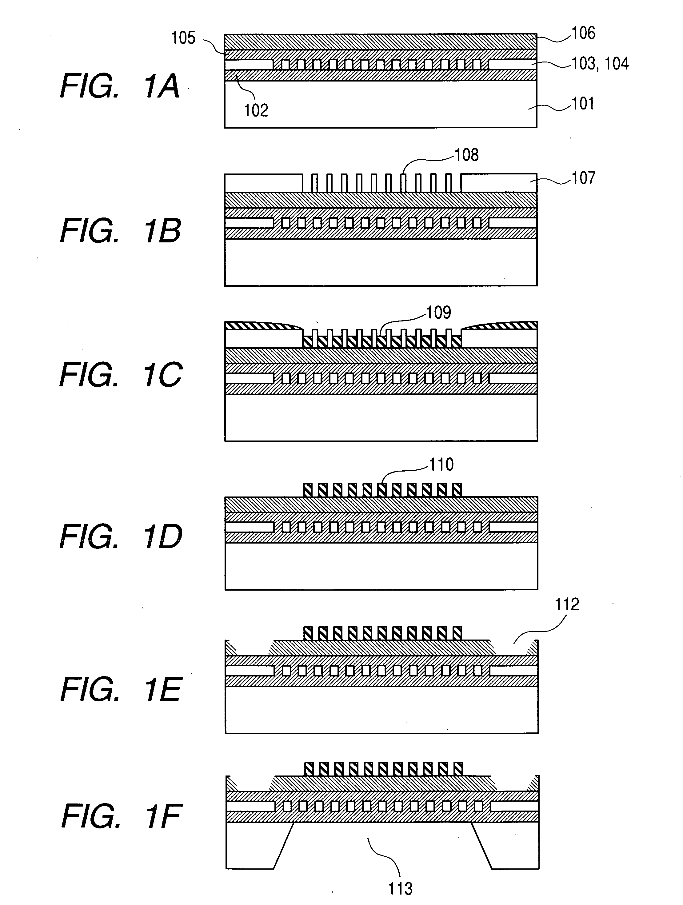
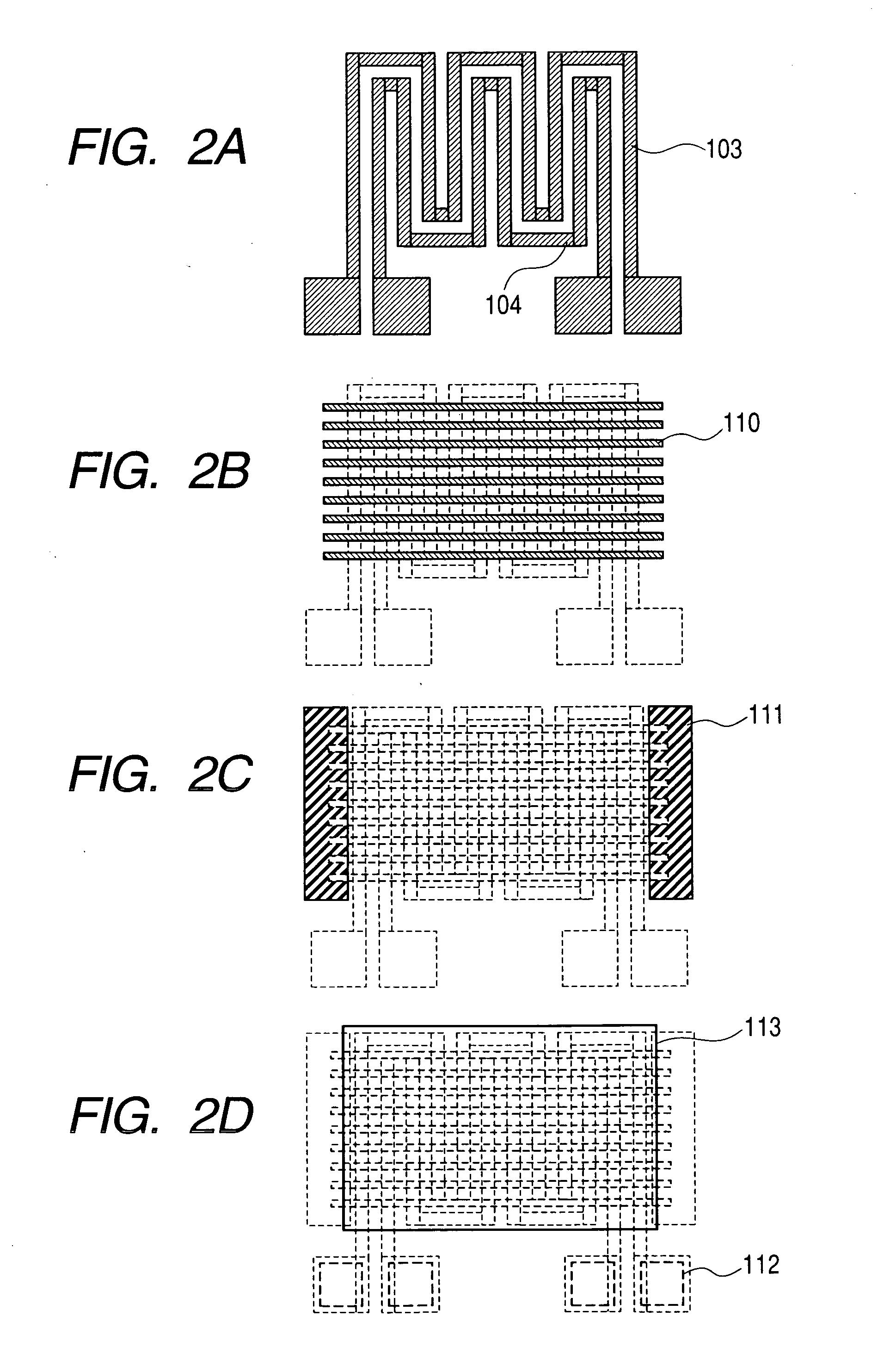
[0049]FIGS. 1A to 1F display schematic drawings illustrating a manufacturing process according to this embodiment using the cross-sections of the sensor. First of all, as shown in FIG. 1A, after a silicon oxide film 102 is formed on the surface of a Si substrate 101, for instance, by patterning a poly crystalline silicon thin film using a conventional lithography means with ultraviolet exposure through a mask, a heater circuit 103 and a temperature sensor circuit 104 are formed on the predetermined sensor area. Afterwards, the entire body mentioned above is coated with a Si oxide film 105 and Si nitride film 106.

[0050] Next, as shown in FIG. 1B, after a 150 nm thick Si oxide film 107 is deposited as a base film to form a ceramic pattern, a predetermined anti-reflection coating film and a resist film are coated, and a resist pattern having 60 nm of line-and-space is formed by exposing and developing it using ArF reduction projection exposure equipment with the numerical aperture of ...

second embodiment

[0074] Next, a method will be described for integrating in the monolith the sensor described in the first embodiment with an integrated circuit. FIGS. 7A to 7F are schematic drawings which illustrate a manufacturing process of an integrated gas sensor in which a sensor described in this embodiment and an integrated circuit are integrated in the monolith. First, as shown in FIG. 7A, an integrated circuit transistor 203 is fabricated by using a conventional CMOS integrated circuit process in a predetermined integrated circuit region 202 on the Si substrate 201. That is, a contact is formed, which consists of a well formation, an isolation by a field oxide film (a trench isolation may be acceptable), a gate oxide film, a gate, a source by a diffusion layer, a drain, and a high-melting point metallic plug. Moreover, herein, a first circuit may be formed to connect the integrated circuit transistor pair, if necessary.

[0075] On the other hand, in the predetermined sensor region 204 on th...

third embodiment

[0084] In an application of a gas sensor, operation for a long period of time without dependence on external energy is often required. For instance, it is necessary to operate it stably for several years using a dry battery. In this case, in addition to the stability of the sensor characteristics themselves, low power consumption is important. Since the power consumption of a ceramic gas sensor is controlled by the heater used to heat the sensor, two points are necessary to make it energy-saving, that is, (1) reducing the heat capacity of the heater and (2) reducing the thermal radiation from the heater portion. Although the priority of the above-mentioned (1) and (2) depends on the operation sequence of the sensor, both (1) and (2) can be achieved by making the heater smaller, in any case.

[0085] Concretely, it is necessary to reduce the volume of the heater, the surface area, the contact parts between the heater and the surrounding areas thereof. However, for this purpose, a surfa...


PUM

PropertyMeasurementUnit
widthaaaaaaaaaa
thickaaaaaaaaaa
thickaaaaaaaaaa

Abstract

The compatibility of increased sensitivity with both reliability and durability was difficult, since in a gas sensor composed of polycrystalline grains or ceramic particles, there is a trade-off relationship between increasing sensitivity through particle size reduction and change with time due to grain growth. Moreover, it was difficult to integrate a ceramic sensor with high sensitivity, high durability and high reliability with a Si integrated circuit in the monolith. A gas sensor is composed of an artificial nano-structure ceramic film where a change in the ceramic structure due to grain growth, etc. does not occur because of heat. The ceramic thin film is formed to a pattern shaped template on a nanometer level by using a sol-gel method and cured adequately to form precisely. Moreover, the above-mentioned gas sensor is integrated with an integrated circuit in the monolith.

Description

CLAIM OF PRIORITY [0001] The present application claims priority from Japanese application JP 2005-041537 filed on Feb. 18, 2005, the content of which is hereby incorporated by reference into this application. FIELD OF THE INVENTION [0002] The present invention relates to a gas sensor composed of ceramics. More particularly, it relates to a technology integrating a ceramic sensor and a semiconductor integrated circuit. BACKGROUND OF THE INVENTION [0003] In the environment surrounding a variety of industrial fields and daily life, it is very important to detect various gases which are dangerous, harmful to or unpleasant for human body, or which destroy the global environment. Moreover, sensing the concentration of gases is required for controlling an automobile engine. On the other hand, attempts to diagnose the health condition of the human body using gases have been reported. A ceramic gas sensor is one of the typical methods for sensing gas concentration. This sensor uses the chan...

Claims


Application Information

Patent Timeline
Patent Type & Authority Applications(United States)
IPC IPC(8): G01N27/26
CPCG01N27/128
Inventor FUKUDA, HIROSHI
Owner HITACHI LTD
Why Eureka
Try Eureka