
Threaded joint for steel pipes

a threaded joint and steel pipe technology, applied in the direction of hose connection, screw threaded joint, mechanical apparatus, etc., can solve the problems of increasing the cost of steel pipe threaded joints, and increasing the adhesion. , the effect of increasing the galling resistan

Inactive Publication Date: 2006-09-07
NIPPON STEEL CORP
View PDF10 Cites 30 Cited by
  • Summary
  • Abstract
  • Description
  • Claims
  • Application Information

AI Technical Summary

Benefits of technology

[0019] This invention provides a threaded joint for steel pipes having excellent galling resistance and capable of avoiding worsening of surface appearance. The threaded joint can be used without application of a compound grease having harmful effects on the global environment such as sea life and on humans. The threaded joint does not exhibit a marked decrease in galling resistance even if a rust preventive oil is applied to the inner and outer surfaces of a pipe in order to prevent corrosion during shipment and storage, nor a marked decrease in galling resistance or worsening in appearance even if these surfaces of a pipe are exposed to condensed water or rainwater during shipment and storage.
[0020] According to the present invention, by forming a nonporous solid corrosion protective coating which does not contain solid particles atop a solid lubricating coating formed on the contact surfaces of a threaded joint, a threaded joint for steel pipes can be provided which has excellent galling resistance in an unlubricated state (without application of a compound grease) and with no significant decrease in performance during shipment or storage.

Problems solved by technology

During the process of lowering tubing or casing into a gas or oil well, due to various problems, there are cases in which it is necessary to loosen a threaded joint which has been once fastened to connect two pipes, to lift the pipes and the threaded joint out of the well, to refasten the pipes with the joint, and then relower them.
However, as described below, the use of a compound grease poses the threat of harmful effects on the environment and humans.
When fastening a threaded joint, grease which has been applied is washed off or overflows to the exterior surface, and there is the possibility of the grease causing harmful effects on the environment and especially on sea life, particularly from harmful heavy metals such as lead.
In addition, the process of applying a compound grease worsens the working environment, and there is a concern of harmful effects on humans.
However, in each of the above-described threaded joints designed for use in an unlubricated state in the prior art, the solid lubricating coating which is the outermost layer is a coating containing solid lubricant particles in a resin, which, as described below, causes some problems in its actual use.
In addition, the inner and outer surfaces of the steel pipe become wetted by water supplied from condensation of moisture or rainfall during transport and storage, and this water also penetrates in the inside of the protectors.
As a result, the solid lubricating coating cannot exhibit its function adequately, and there is the possibility of the galling resistance of the threaded joint markedly decreasing.
It is conjectured that this is due to a decrease in lubricating performance due to a chemical reaction between the rust preventive oil and the solid lubricant or the binder, or due to an extreme pressure being generated in the rust preventive oil which is confined in the lubricating coating by the pressure which is generated at the time of fastening of a threaded joint, thereby resulting in the breakdown of the bonding of the lubricating coating.
As a result, there is the possibility of the lubricating properties of the coating decreasing due to a reaction of water with the solid lubricant or of the surface appearance being worsened particularly when the coating contains copper.
These problems caused by a rust preventive oil or water result from the fact that the outermost porous solid lubricating coating is not effectively protected.
A corrosion protective coating formed underneath the solid lubricating coating for protection of the steel pipe itself as disclosed in WO 2004 / 033951 cannot solve these problems.

Method used


Image

  • Threaded joint for steel pipes
  • Threaded joint for steel pipes
  • Threaded joint for steel pipes

Examples


example 1

[0094] The pin and box surfaces of a carbon steel threaded joint having composition A shown in Table 1 were separately subjected to the following surface treatment.

[0095] The box surfaces which had been finished by machine grinding (surface roughness of 3 μm) were immersed for 10 minutes in a manganese phosphating solution (a manganese phosphate-type phosphating solution) at 80-95° C. for preparatory surface treatment to form a primary coating which was a manganese phosphate coating with a thickness of 15 μm. On the primary coating, a solid lubricating coating with a thickness of 30 μm was formed from an epoxy resin containing graphite powder with an average particle diameter of 10 μm and copper flaky powder with a maximum length of 15 μm. The mass ratio of graphite to epoxy resin (M in Table 2) in the solid lubricating coating was 0.6:1, and the mass ratio of copper powder to graphite (N in Table 2) therein was 0.2:1. A solid corrosion protective coating formed solely of an epoxy ...

example 2

[0097] The pin and box surfaces of a carbon steel threaded joint having composition A shown in Table 1 were separately subjected to surface treatment exactly in the same manner as described in Example 1.

[0098] Thus, the box surfaces had an innermost manganese phosphate coating, an intermediate solid lubricating coating containing graphite powder and copper powder in an epoxy resin, and an outermost solid corrosion protective coating of an epoxy resin. The pin surfaces had a lower zinc phosphate coating and an upper solid corrosion protective coating of an epoxy resin.

[0099] The box surfaces were exposed to the salt spray test. Upon observation of the box surfaces after the salt spray test for 100 hours, no change in the surface appearance was found. In the fastening and loosening test, as shown in Table 3, there was no occurrence of seizing or galling during 10 cycles of fastening and loosening, and the results were extremely good.

example 3

[0100] The pin and box surfaces of a threaded joint made of the Cr—Mo steel having composition B in Table 1 were separately subjected to the following surface treatment.

[0101] The box surfaces which had been finished by machine grinding (surface roughness of 3 μm) were subjected to pickling for preparatory surface treatment to obtain a surface roughness of 10 μm. On the box surfaces which had been treated in this manner, a solid lubricating coating with a thickness of 30 μm was formed from an epoxy resin containing molybdenum disulfide powder with an average particle diameter of 5 μm. The mass ratio M of molybdenum disulfide to epoxy resin in the solid lubricating coating was 0.7:1. A solid corrosion protective coating formed solely of epoxy resin was formed to a thickness of 20 μm atop this solid lubricating coating.

[0102] The pin surfaces which had been finished by machine grinding (surface roughness of 3 μm) were subjected to pickling for preparatory surface treatment to obtain...


PUM


Abstract

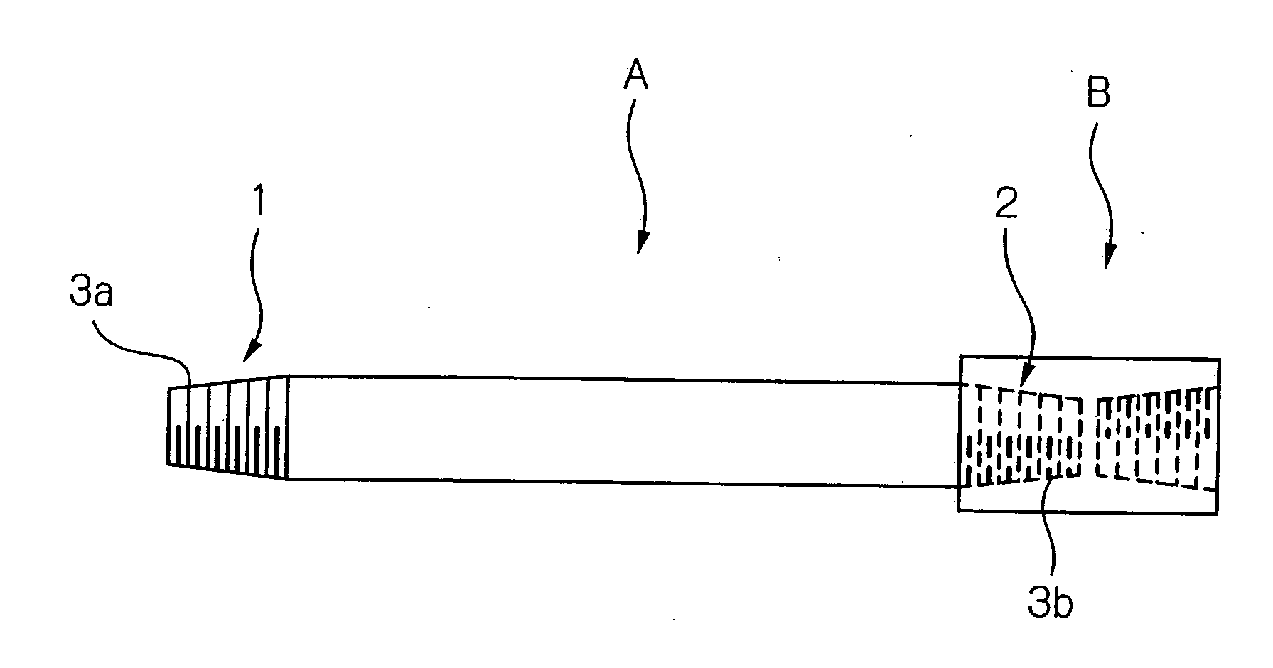
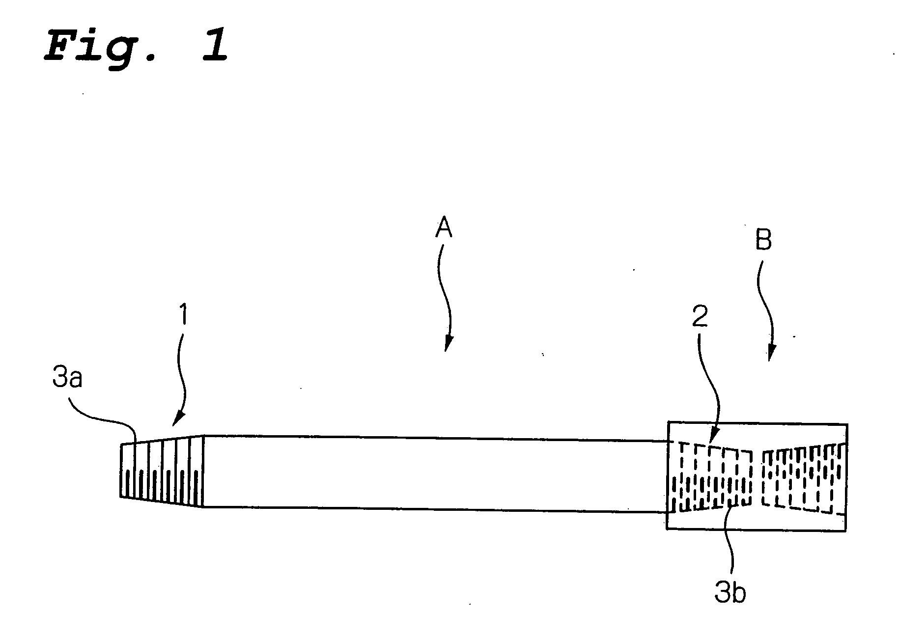
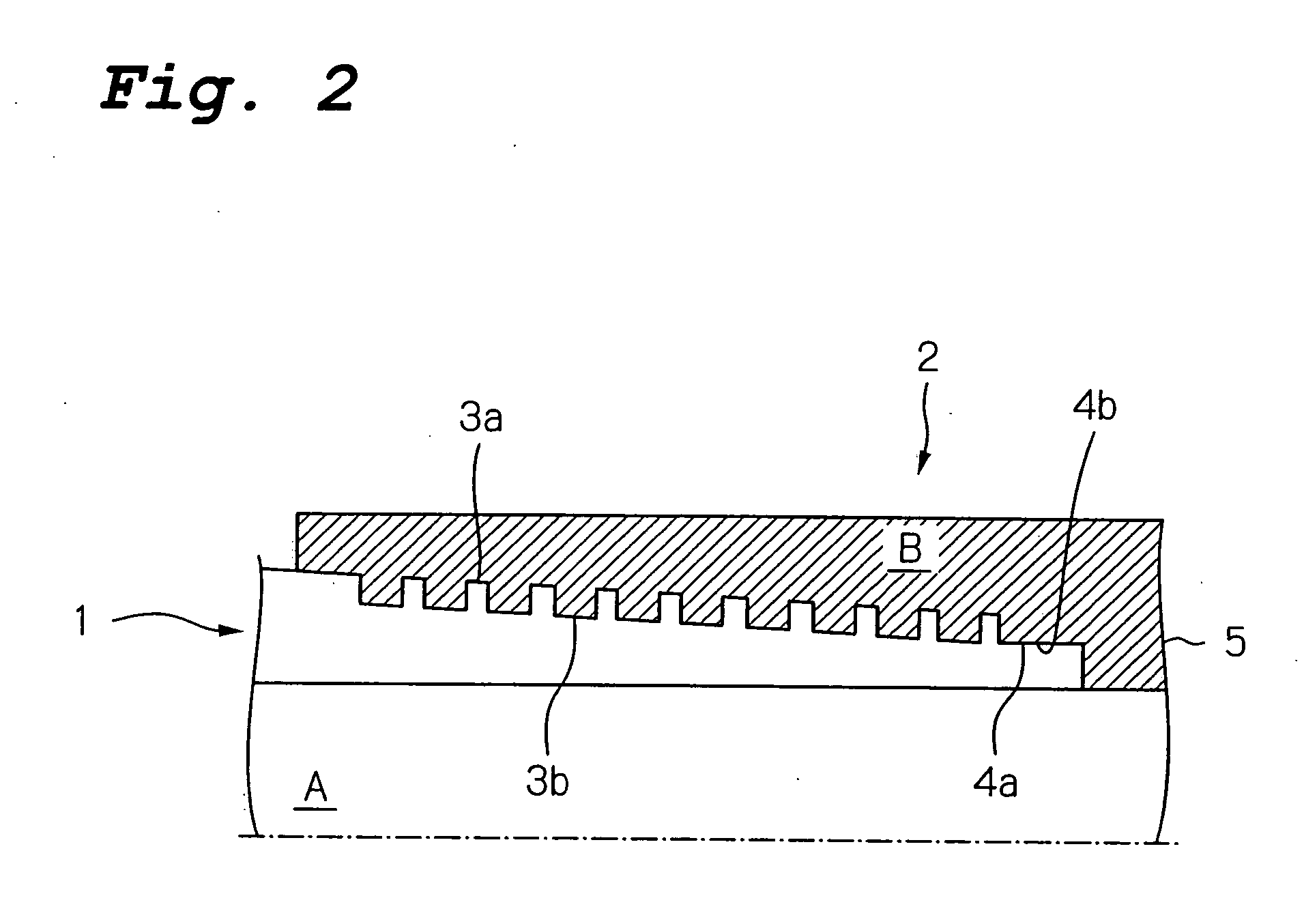
A threaded joint for steel pipes comprises a pin (1) and a box (2) each having a threaded portion (3a or 3b) and an unthreaded metal-to-metal contact portion (4a or 4b) as contact surfaces which contact each other when the joint is fastened. The contact surfaces (3a and 4a and / or 3b and 4b) of at least one of the pin (1) and the box (2) are coated with a lower layer of a solid lubricating coating containing a solid lubricating powder (e.g., molybdenum disulfide, tungsten disulfide, or graphite) and a binder (e.g., an epoxy or other organic resin) and an upper layer of a solid corrosion protective coating formed by an organic resin which does not contain solid particles.

Description

TECHNICAL FIELD [0001] This invention relates to a threaded joint for steel pipes which can exhibit excellent galling resistance with certainty without being coated with a compound grease which has been applied to threaded joints when connecting OCTG (oil country tubular goods). The threaded joint for steel pipes according to the present invention can avoid the harmful effects on the global environment and on humans caused by compound grease. BACKGROUND ART [0002] OCTG such as tubing and casing used in the excavation of gas wells and oil wells are usually connected to each other by threaded joints. In the past, the depth of oil wells was generally 2,000-3,000 meters, but in deep oil wells such as recent offshore oil fields, the depth of oil wells reaches 8,000-10,000 meters. In the environment of use, threaded joints for connecting such OCTG are subjected to various forces, such as axial tensile forces caused by the weight of the OCTG and the threaded joints themselves, the combinat...

Claims


Application Information

Patent Timeline
Patent Type & Authority Applications(United States)
IPC IPC(8): F16L15/00
CPCC10M103/02C10M103/06C10M2201/041C10M2201/0413C10M2201/066C10M2201/0663C10N2240/22C10N2250/08F16L15/001F16L58/182C10N2040/34C10N2050/08
Inventor IMAI, RYUICHIGOTO, KUNIOTAKANASHI, KAORUOGAWA, YASUHIRO
Owner NIPPON STEEL CORP
Learn More