Negative working light sensitive planographic printing plate material and planographic printing plate manufacturing process

a technology of planographic printing plate and negative working light, applied in the direction of auxillary/base layers of photosensitive materials, instruments, photosensitive materials, etc., can solve the problems of insufficient hardening of light sensitive layers at exposed portions, insufficient printing durability, and inability to achieve sufficient printing durability, etc., to achieve excellent water developability, high printing durability, and high sensitivity

Inactive Publication Date: 2006-09-21
KONICA MINOLTA MEDICAL & GRAPHICS INC
View PDF4 Cites 4 Cited by
  • Summary
  • Abstract
  • Description
  • Claims
  • Application Information

AI Technical Summary

Benefits of technology

[0200] As the laser for imagewise exposing the light sensitive planographic printing plate material of the invention, there is a laser emitting infrared or near-infrared light, i.e., light with a wavelength of from 700 to 1500 nm. Preferred examples thereof include a YAG laser and a semiconductor laser. A laser having emission wavelength regions of from 700 to 1200 nm is preferably used in displaying the advantageous effects of the processless planographic printing plate material of the invention.
[0201] In a printing process employing the processless printing plate material of the invention, for example, the planographic printing plate material is provided along the outer peripheral wall of the drum of a printing press, and subjected to scanning exposure in the rotational direction (in the main scanning direction) of the drum, employing one or several lasers located outside the cylinder, while moving the lasers in the normal direction (in the sub-scanning direction) to the rotational direction of the drum to form an image.
[0202] As the light source, lasers having an emission wavelength regions of from ultraviolet to short visible wavelength regions can be used. Examples of such lasers include a He—Cd laser (441 nm), a combination of Cr:LiSAF and SHG crystals (430 nm) as a solid laser, and KnbO3, ring resonator (430 nm), AlGaInN (350-350 nm) or AlGaInN semiconductor laser (InGaN type semiconductor laser available on the market, 400-410 nm) as a semiconductor type laser.
[0203] As a laser scanning method of lasers used in the invention, there are a method of laser scanning on an outer surface of a cylinder, a method of laser scanning on an inner surface of a cylinder, and a method of laser scanning on a plane. In the method of laser scanning on an outer surface of a cylinder, laser beam exposure is conducted while a drum around which a recording material is wound is rotated, in which main scanning is represented by the rotation of the drum, while sub-scanning is represented by the movement of the laser beam. In the method of laser scanning on an inner surface of a cylinder, a recording material is fixed on the inner surface of a drum, a laser beam is emitted from the inside, and main scanning is carried out in the circumferential direction by rotating a part of or an entire part of an optical system, while sub-scanning is carried out in the axial direction by moving straight a part of or an entire part of the optical system in parallel with a shaft of the drum. In the method of laser scanning on a plane, main scanning by means of a laser beam is carried out through a combination of a polygon mirror, a galvano mirror and an Fθ lens, and sub-scanning is carried out moving a recording medium. The cylinder outer surface laser scanning method and the cylinder inner surface laser scanning method are suitable for high density image recording, since it is easier to increase accuracy of an optical system. The cylinder outer surface laser scanning method is especially preferred in employing laser energy effectively, and in designing easily the optical system including the laser used.
[0204] In the invention, imagewise exposure is carried out at a plate surface energy (an exposure energy at the surface of the planographic printing plate material) of from 10 to 500 mJ / cm2, and more preferably from 10 to 300 mJ / cm2. This exposure energy can be measured, employing a laser power meter PDGDO-3W produced by Ophir Optronics Inc. (Processless Printing Plate Material)
[0205] The negative working light sensitive planographic printing plate material of the invention can be subjected to conventional development, but is preferably used as a processless printing plate material. Next, a printing process will be explained which employs, as the processless printing plate material, the light sensitive planographic printing plate material of the invention. (Image Formation)

Problems solved by technology

A negative working light sensitive planographic printing plate material comprising conventional polymeric binders described above has problems in that sufficient printing durability is not obtained.
When an exposure scanning speed is increased in order to increase productivity, exposure energy per unit area of the light sensitive layer surface of the planographic printing plate material is small, resulting in an insufficiently hardened light sensitive layer at exposed portions, which is susceptible to damage by alkali components in a developer.
Light sensitive compositions, comprising modified polyvinyl alcohol having in the side chain a radically polymerizable group, are disclosed in Japanese Patent O.P.I. Publication Nos. 2000-181062 and 2000-506282, however, these compositions are not those used in a planographic printing plate material.
However, the high content of the radically polymerizable group in the modified polyvinyl alcohol reduces the content of the hydroxyl group in the modified polyvinyl alcohol providing water developability, resulting in problems of lowering developability.
This technique somewhat improves printing durability and developability, however, it does not sufficiently meet demands of the market.
However, a conventional printing process employing a processless printing plate material has problems which are insufficient in ink receptivity at initial printing stage or in printing image quality, which does not meet high level of requirements of printing industries.
This process has big problems particularly in a planographic printing plate employing an aluminum support.

Method used


Image

  • Negative working light sensitive planographic printing plate material and planographic printing plate manufacturing process
  • Negative working light sensitive planographic printing plate material and planographic printing plate manufacturing process
  • Negative working light sensitive planographic printing plate material and planographic printing plate manufacturing process

Examples


example 1

(Synthesis 1)

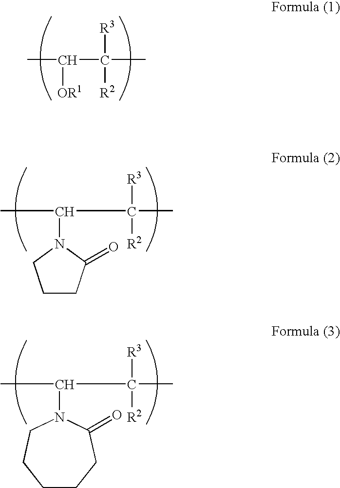
[0242] N-Vinyl pyrrolidone of 65.5 parts (0.59 mol %), 100 parts of ethanol and 1.23 parts of α,α′-azobisiso-butylonitrile were placed in a three neck flask under nitrogen atmosphere. The resulting mixture was reacted under nitrogen atmosphere for 6 hours at 80° C. in an oil bath, while dropwise adding 35.0 parts (0.41 mol %) of methacrylic acid.

[0243] After that, the reaction mixture was added with one part of triethylbenzylammonium chloride and 28 parts (0.2 mol %) of glycidyl methacrylate, and reacted at 25° C. for 3 hours. Thus, Polymer 1 as a polymeric binder was obtained. Polymer 1 had a weight average molecular weight of 55,000, measured according to GPC, and had an acid value of 95.

(Synthetic 2)

[0244] Methyl vinyl ether-maleic anhydride copolymer Gantrez AN-119 (produced by ISP Japan Co., Ltd.) of 64.0 parts (0.82 mol %), 100 parts of isopropanol, 1 part of triethylbenzylammonium chloride, and 28 parts (0.2 mol %) of glycidyl methacrylate were placed in a ...

example 2

[0269] Next, the following polymerizable light sensitive layer coating solution was prepared, and evaluation described later was made.

>Polymeric binder (Polymer 1)65.0partsCyanine dye-14.0partsPolymerization initiator (I)amount shownin Table 3Polymerization initiator (II)amount shownin Table 3Addition polymerizable ethylenically15.0partsunsaturated monomer (Compound A)Polyethylene glycol #200 dimethacrylate10.0parts(NK ESTER-4G, produced by Shinnakamura KagakuKogyol Co., Ltd.)Phthalocyanine pigment MHI 4543.0parts(produced by Mikuni Sikisosha, 30% MEK dispersion)Hindered amine stabilizer0.5parts(LS 770 produced by Mitusi Life-Tech Co., Ltd.)Fluorine-contained surfactant0.5parts(F-178K produced by Dainippon ink Kagaku Kogyo Co.,Ltd.)Cyclohexanone (bp. 155° C.)550partsIsopropyl alcohol350parts

[0270] A planographic printing plate material-sample was prepared in the same manner as in Example 1, except that the polymerizable light sensitive layer coating solution above was used. Thus, ...


PUM

PropertyMeasurementUnit
Tgaaaaaaaaaa
Tgaaaaaaaaaa
Tgaaaaaaaaaa

Abstract

Disclosed is a negative working light sensitive planographic printing plate material comprising a support and provieded thereon, a light sensitive layer containing a spectral sensitizing agent, a polymerization initiator, a polymerizable compound, and a polymer as a polymeric binder, wherein the polymer has in the molecule a monomer unit with a polymerizable group and at least one of a polyvinyl ether chain, a polyvinyl pyrrolidone chain and a polyvinyl caprolactam chain.

Description

[0001] This application is based on Japanese Patent Application No. 2005-077418, filed on Mar. 17, 2005 in Japanese Patent Office, the entire content of which is hereby incorporated by reference. FIELD OF THE INVENTION [0002] The present invention relates to a negative working light sensitive planographic printing plate material for so-called a computer-to-plate system (hereinafter referred to as CTP system), and particularly to a light sensitive planographic printing plate material suitable for so-called a processless plate capable of being developed with water and of being developed on a printing press and a process of manufacturing a planographic printing plate therefrom. BACKGROUND OF THE INVENTION [0003] Presently, digital technique electronically processing, storing and outputting image information employing a computer has spread. In a plate making system of a planographic printing plate for off-set printing, a CTP system, which writes a digital image directly on a light sensi...

Claims


Application Information

Patent Timeline
Patent Type & Authority Applications(United States)
IPC IPC(8): G03C1/76
CPCB41C1/1008G03F7/033G03F7/0388G03F7/3035B41C1/1016B41C2201/02B41C2201/10B41C2201/12B41C2201/14B41C2210/04B41C2210/08B41C2210/20B41C2210/22B41C2210/24
Inventor KUROKI, TAKAAKI
Owner KONICA MINOLTA MEDICAL & GRAPHICS INC
Why Eureka
Try Eureka