
Fully-implantable cardiac recovery system

a cardiac recovery and fully implantable technology, applied in the field of fully implantable cardiac recovery systems, can solve the problems of electrodes coming into electrical contact with each other, and achieve the effects of reducing systemic blood pressure, increasing systemic blood pressure, and regulating blood pressur

Inactive Publication Date: 2006-09-28
GROSS +1
View PDF43 Cites 43 Cited by
  • Summary
  • Abstract
  • Description
  • Claims
  • Application Information

AI Technical Summary

Benefits of technology

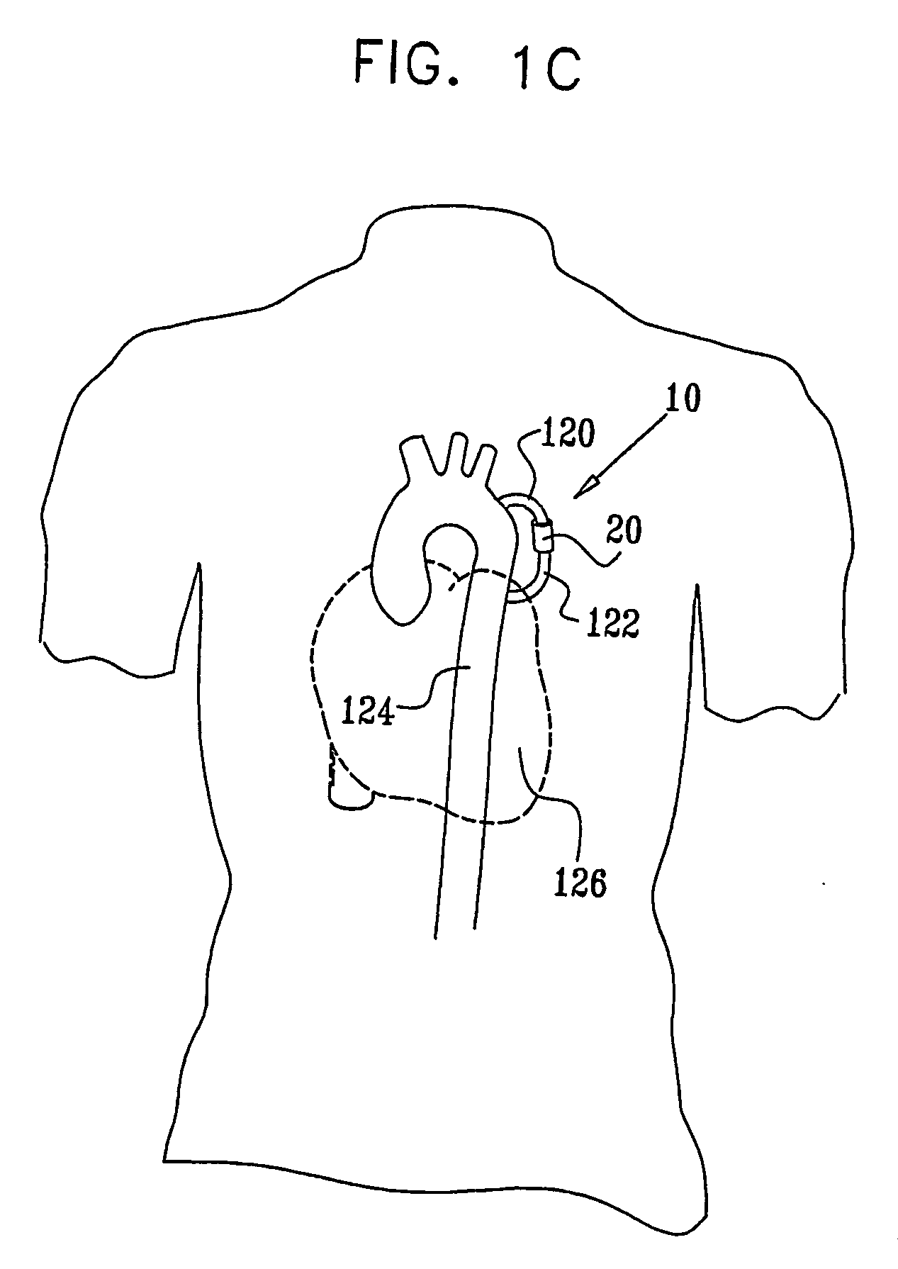
[0034] In some embodiments of the present invention, an extracardiac fully-implantable cardiac recovery device comprises an inflatable bladder coupled to the descending aorta, e.g., the descending thoracic aorta, or a peripheral artery of a subject, such as an iliac artery or a left subclavian artery. The device, operating in a counterpulsation mode, regulates blood pressure in synchronization with the cardiac cycle of the subject by (a) accepting blood into the bladder immediately prior to and during systole, thereby reducing systemic blood pressure, and (b) ejecting the blood from the bladder during diastole, thereby increasing systemic blood pressure. The reduction in blood pressure prior to systole generally increases cardiac stroke volume by decreasing afterload, and reduces heart workload. The increased diastolic blood pressure generally increases coronary perfusion and lowers venous blood pressure, thereby reducing heart preload. Longer-term usage of the device generally improves heart contractility, reversing the vicious cycle that characterizes heart failure. The device is typically configured to operate as a heart assist device and / or a blood pressure regulation device, and is useful for treating subjects suffering from cardiovascular conditions such as heart failure, hypertension, angina, and / or ischemia. The device is typically suitable for long-term implantation and usage, including when the subject is active.
[0035] In some embodiments of the present invention, the cardiac recovery device comprises a regulation unit, adapted to regulate and synchronize the contraction and expansion of the bladder with the cardiac cycle. The regulation unit typically comprises a motor, such as a linear motor, or a compliance-regulation spring. For some applications, the regulation unit comprises both a motor and a spring, in which case the spring typically supports the action of the motor, thereby reducing the energy consumption of the motor. The device typically further comprises a piston, which is driven against the bladder by the motor and / or the spring, and a fixed case adapted to: (a) limit the expansion of the bladder in a direction opposite that of the regulation unit, and (b) cause the expansion of the bladder, which is induced by the high pressure during systole, to perform work on the spring (e.g., compress or extend the spring). For some applications, the piston is driven by hydraulic pressure instead of or in addition to the motor. In some embodiments of the present invention, the bladder comprises a flexible, non-elastic material. In other embodiments, including embodiments in which the device does not comprise a regulation unit, the bladder comprises an elastic material.
[0036] In some embodiments of the present invention, the cardiac recovery device is adapted to be coupled to a pulmonary vein of the subject. In these embodiments, the device further comprises a unidirectional valve, configured to substantially prevent backflow of blood from the pulmonary vein to the lungs. The device thus treats diastolic heart failure by increasing the flow of blood from one or both of the lungs to a left atrium of the subject.

Problems solved by technology

However, if either of the layers is breached, electrically conductive biological fluid enters the chamber, causing the electrodes to come into electrical contact with one another.

Method used


Image

  • Fully-implantable cardiac recovery system
  • Fully-implantable cardiac recovery system
  • Fully-implantable cardiac recovery system

Examples


Embodiment Construction

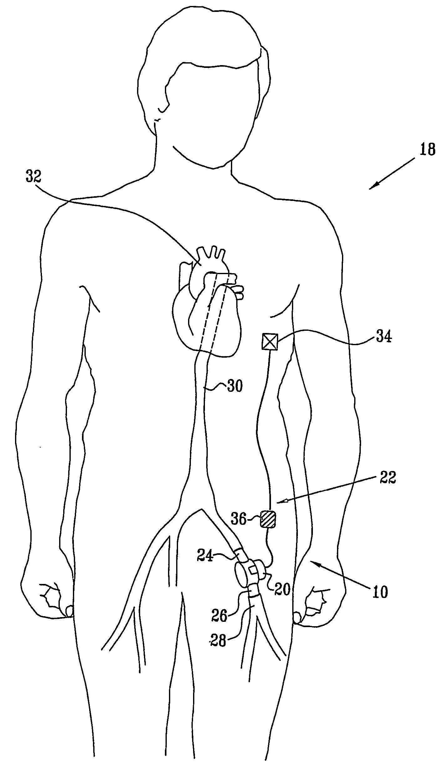
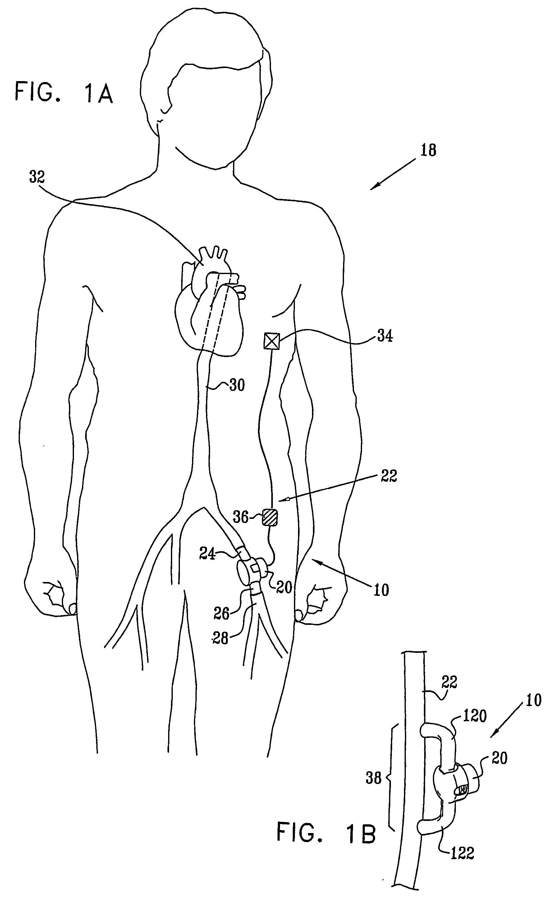
[0231]FIG. 1A is a pictorial view of a cardiac recovery system 10, comprising a cardiac recovery device 20 implanted in a blood vessel 22 on the arterial side of the circulation of a subject 18, in accordance with an embodiment of the present invention. Device 20 is generally implanted in arterial blood vessel 22 during a simple surgical procedure in which the artery is cut, and respective cut ends of the artery are attached to an inflow conduit 24 and an outflow conduit 26 of the device, so that blood flowing through the artery passes through device 20. Device 20 is typically implanted in an iliac artery 28, a descending aorta 30, an ascending aorta 32, or another peripheral artery of subject 18, such as a femoral artery. For some applications, system 10 comprises an implanted or external control unit 36, and one or more implantable or external sensors 34, which are typically adapted to generate an electrocardiogram (ECG) signal.

[0232]FIG. 1B is a pictorial view of an alternative ...


PUM


Abstract

Apparatus (20) is provided including an inflatable bladder (40), adapted to be coupled to a blood vessel (22) of a subject (18) carrying oxygenated blood, such that an interior of the bladder (40) is in fluid communication with the blood. The apparatus also includes a piston (48) in mechanical communication with the bladder (40); a motor (60), adapted to synchronize contraction and expansion of the bladder (40) with a cardiac cycle of the subject (18) by applying a motor force to the piston (48); and a spring (54), adapted to apply a spring force to the piston (48).

Description

CROSS-REFERENCES TO RELATED APPLICATIONS [0001] This application claims the benefit of U.S. Provisional Application 60 / 449,495, filed Feb. 24, 2003, entitled, “Fully-implantable cardiac recovery system,” which is assigned to the assignee of the present application and is incorporated herein by reference.FIELD OF THE INVENTION [0002] The present invention relates generally to implantable medical devices, and specifically to methods and apparatus for implantable devices for treating heart failure, hypertension, and other cardiovascular conditions. BACKGROUND OF THE INVENTION [0003] Heart failure is a chronic cardiac condition characterized by a deficiency in the ability of the heart to pump blood. Decreased cardiac output to the systemic circulation typically increases venous blood pressure, which often leads to blood backing up in the lungs. Low cardiac output also results in decreased blood perfusion to organs, such as the liver, kidney, brain, and heart itself. Over time, the effec...

Claims


Application Information

Patent Timeline
IPC IPC(8): A61M1/12A61BA61M60/268A61M60/438A61M60/531A61M60/554A61M60/857A61M60/871A61N1/362
CPCA61M1/1037A61M1/107A61M1/1055A61M1/122A61M2205/33A61M2205/3303A61M2205/8243A61M60/274A61M60/554A61M60/438A61M60/531A61M60/152A61M60/148A61M60/896A61M60/268A61M60/446
Inventor GROSSGEFEN, RA'ANAN
Owner GROSS
Learn More