Pulsed-inertial electric motor

a technology of electric motors and electric motors, applied in the direction of acyclic motors, windings, dc interrupters, etc., can solve the problems of complex control systems and high-voltage power supplies, motor wheels offering no prospects for electric energy recovery, and high heat evolution, etc., to achieve simple design, increase performance characteristics, and high reliability

a technology of electric motors and electric motors, applied in the direction of acyclic motors, windings, dc interrupters, etc., can solve the problems of complex control systems and high-voltage power supplies, motor wheels offering no prospects for electric energy recovery, and high heat evolution, etc., to achieve simple design, increase performance characteristics, and high reliability

US20060232154A1Inactive Publication Date: 2006-10-19ULTRA MOTOR CO LTD

Image

  • Pulsed-inertial electric motor
  • Pulsed-inertial electric motor
  • Pulsed-inertial electric motor

Examples


example 1

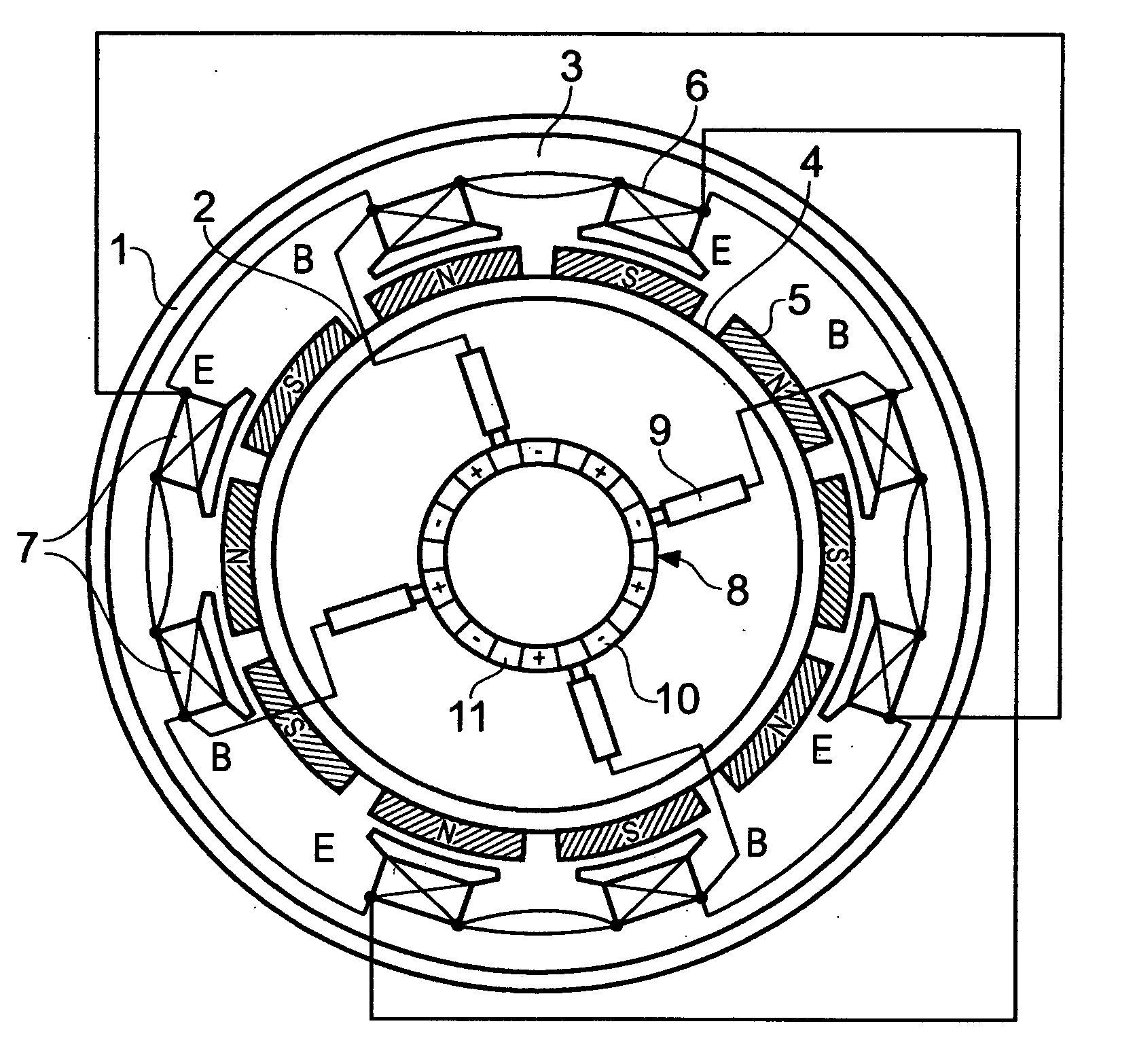
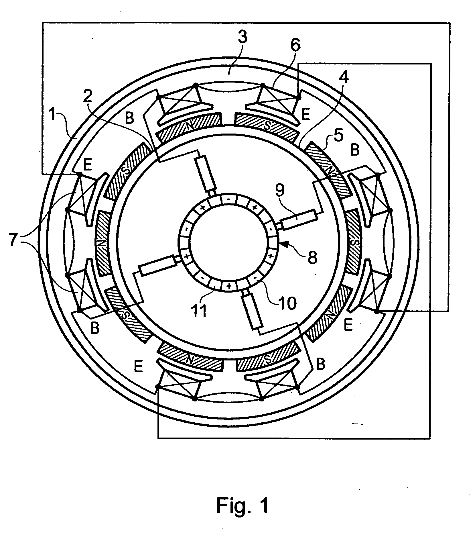
[0041] A prototype electric motor was constructed with a stator involving 22 permanent magnets, a rotor involving three pairs of electromagnets, and the coils in each electromagnet containing 68 turns of an 1.06-diam wire. The motor has the following parameters: diameter, 300 mm; width 50 mm; weight, 7.5 kg; power consumption, 240 W; supply voltage, 24 V; torque, 9.6 N / m.

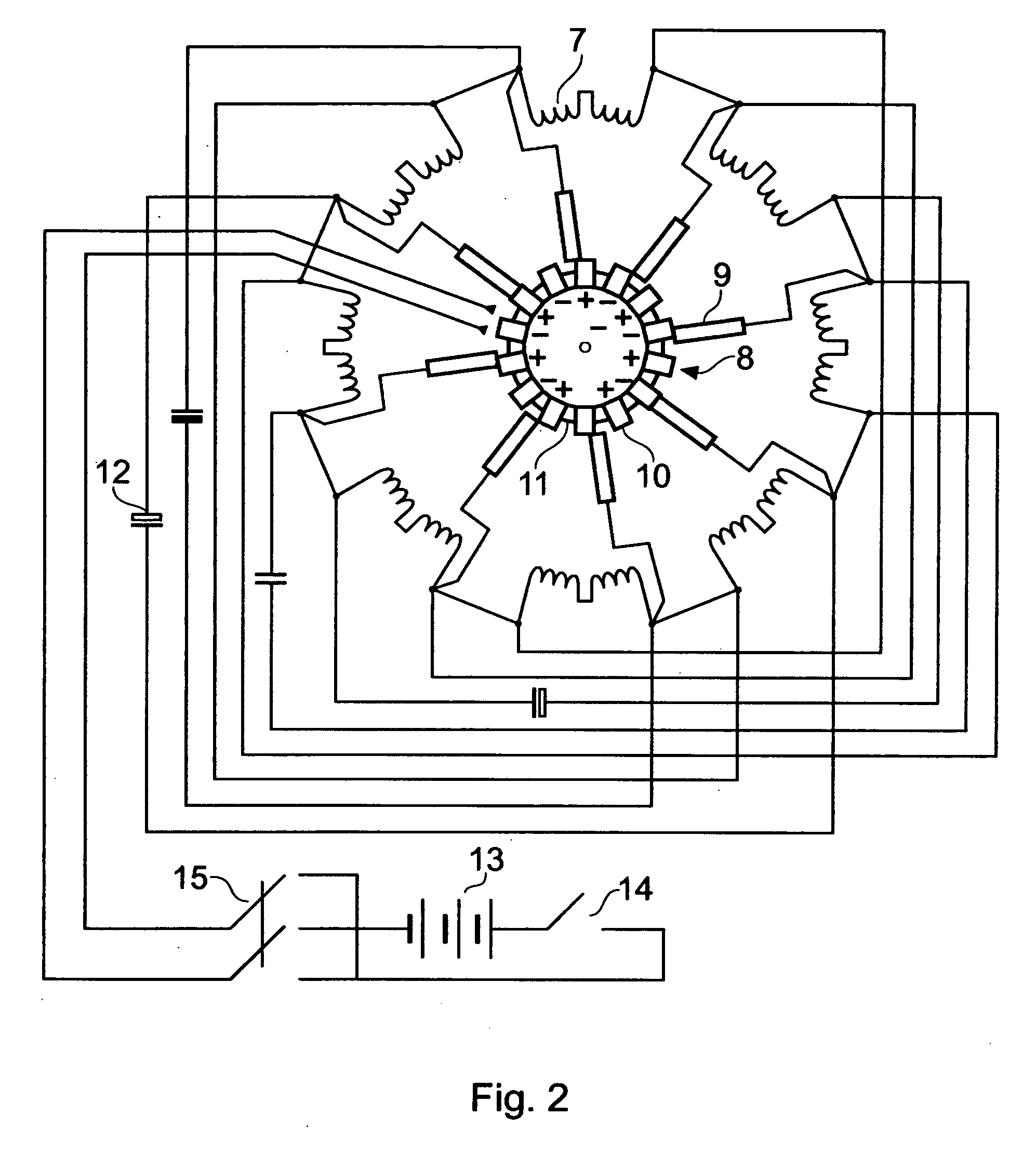
[0042] This motor was used as a motor-wheel in a bicycle of the STELS type with 26″ wheels. The current source comprised a pair of 12-V storage batteries, each with a capacity of 20 A / h. The bicycle with an electric drive based on the proposed motor was tested to show the following characteristics: weight-carrying capacity, 120 kg; cruising speed, 25 km / h; maximum run (for a storage battery discharged to 10.5 V), 40 km.

example 2

[0043] A prototype electric motor was constructed with a stator involving 22 permanent magnets, a rotor involving five pairs of electromagnets, and the coils in each electromagnet containing 50 turns of an 1.25-diam wire. The motor has the following parameters: diameter, 300 mm; width 60 mm; weight, 9.6 kg; power consumption, 1000 W; supply voltage, 48 V; torque, 40 N / m.

[0044] This motor was used as a motor-wheel in a scooter type with 16″ motorcycle wheels. The current source comprised four 12-V storage batteries, each with a capacity of 20 A / h. The scoter with an electric drive based on the proposed motor was tested to show the following characteristics: weight-carrying capacity, 150 kg; cruising speed, 45 km / h; maximum speed, 60 km / h; maximum run (for a storage battery discharged to 10.5 V), 50 km.

example 3

[0045] A prototype electric motor was constructed with a stator involving 18 permanent magnets, a rotor involving four pairs of electromagnets, and the coils in each electromagnet containing 55 turns of an 1.32-diam wire. The motor has the following parameters: diameter, 306 mm; width 72 mm; weight, 11 kg; power consumption, 1500 W; supply voltage, 48 V; torque, 52 N / m.

[0046] Two such motors were used as motor-wheels in a three-wheel carriage with 16″ motorcycle wheels for a driver and two passengers. The current source comprised four 12-V storage batteries, each with a capacity of 60 A / h. The carriage with an electric drive based on the proposed motor was tested to show the following characteristics: weight-carrying capacity, 500 kg; cruising speed, 45 km / h; maximum speed, 70 km / h; maximum run (for a storage battery discharged to 10.5 V), 70 km.

[0047] All measurements disclosed herein are at standard temperature and pressure, at sea level on Earth, unless indicated otherwise.


PUM


Abstract

The invention relates to electric motors, particularly to low-voltage gearless commutator motors, and can be used as motor-wheels in transportation vehicles and in other technologies. The aim of the present invention is to provide an electric motor with increased performance characteristics, relatively simple design, and high reliability. A pulsed inertial electric motor according to the invention comprises: (i) a stator with circular magnetic conductor on which an even number of permanent magnets are uniformly arranged with a certain pitch; (ii) a rotor separated from the stator by air gap and bearing an even number of electromagnets, each electromagnet consisting of two coils with opposite winding directions connected in series, which are arranged over the circle in pairs one opposite to another; (iii) a collector distributor mounted on the stator body, containing circularly arranged current-conducting plates separated by insulating spacers and connected with alternating polarity to a dc current source, and (iv) current collectors-brushes mounted on the rotor and capable of contacting with plates of the collector distributor, whereby all brushes are connected to identical (beginning or end) terminals of the windings of said electromagnets and interconnected so that the coils in the opposite electromagnets are connected to each other via one identical terminal and to the opposite brushes via another identical terminal, with the number n of permanent magnets in the stator and the number m of electromagnets in the rotor selected so as to obey the relations n=10+4k, m=4+2l, where k is an arbitrary integer (k=0, 1, 2, . . . ) and l is any integer such that 0≦l≦k.

Description

CROSS-REFERENCE TO RELATED APPLICATIONS [0001] This is a continuation-in-part of my U.S. patent application Ser. No. 10 / 824,205, filed 14 Apr. 2004, and incorporated herein by reference, which is a continuation of International Application No. PCT / RU2003 / 00178, filed 18 Apr. 2003, priority of which is hereby claimed, and which is incorporated herein by reference. [0002] Priority of my Russian Patent Application No. 2005110334 filed 11 Apr. 2005, and incorporated herein by reference, is hereby claimed. [0003] U.S. Patent Publication No. US 2004 / 0239204 A1 is incorporated herein by reference. [0004] Priority of my U.S. Provisional Patent Application No. 60 / 512,652, filed 20 Oct. 2003, and incorporated herein by reference, is hereby claimed. [0005] Incorporated herein by reference is my International Application No. PCT / RU2003 / 00178, filed 18 Apr. 2003, and its publication, No. WO 2004 / 091957, published on 28 Oct. 2004.STATEMENT REGARDING FEDERALLY SPONSORED RESEARCH OR DEVELOPMENT [00...

Claims


Application Information

Patent Timeline
19 Oct 2006
Publication
US20060232154A1
IPC
H02K13/00; H02K25/00
CPC
H02K25/00
Inventors
SHKONDIN, VASILY VASILIEVICH