Photomask assembly incorporating a metal/scavenger pellicle frame

a technology of pellicle frame and photomask, which is applied in the field of photomask assemblies, can solve the problems of destroying the patterns transferred to the chips, forming and growing ammonium sulfate crystals under continued laser exposure, and heating the photomask assembly, and achieves the effect of sufficient strength

Inactive Publication Date: 2006-11-02
YAZAKI CORP
View PDF7 Cites 64 Cited by
  • Summary
  • Abstract
  • Description
  • Claims
  • Application Information

AI Technical Summary

Problems solved by technology

The light from such high energy lasers can heat the photomask assembly and trigger certain undesired photochemical and thermal reactions in the pellicle space.
Over time, these reactions can cause the formation and growth of defects (or contaminants) under the pellicle, on the surfaces of photomask assembly components, eventually destroying the patterns transferred to the chips.
These chemicals may leave residues on and / or react with the reticle surfaces during the cleaning process and later cause formation and growth of ammonium sulfate crystals under continued laser exposure.
This results in defects, as described by Grenon et al. in a publication entitled “Reticle Surface Contaminants and Their Relationship to Sub-Pellicle Particle Formation” Proceedings of SPIE Vol. 5256, 23rd Annual BACUS Symposium on Photomask Technology, 1103-1110 (2003).
However, future research might reveal the presence of other defect-forming chemicals or other defect formation and growth mechanisms.
Such chemicals might diffuse into the pellicle space from the outside environment and / or might form by degassing or degradation of the assembly components.
However, this purging is thought to be too slow to eliminate all the problems discussed above within a reasonable processing time.
Also, it is known that soft polymer pellicles can easily degrade when repetitively exposed to light from UV and DUV lasers, causing considerable reduction in light transmittance.
In addition, soft polymer pellicles cannot easily be cleaned and handled.
Although such hard pellicles can solve the cleaning, handling, and degradation problems, they are impermeable to gases and thereby not suitable for purging through the pellicle.
However, these proposals fail to disclose a frame that can effectively remove the harmful chemicals from the pellicle space and at the same time fulfill strict specification requirements of the semiconductor industry for the photomask assembly, without causing additional problems.

Method used


Image

  • Photomask assembly incorporating a metal/scavenger pellicle frame
  • Photomask assembly incorporating a metal/scavenger pellicle frame
  • Photomask assembly incorporating a metal/scavenger pellicle frame

Examples


example 1

Metal Pellicle Frame and Machining of Windows

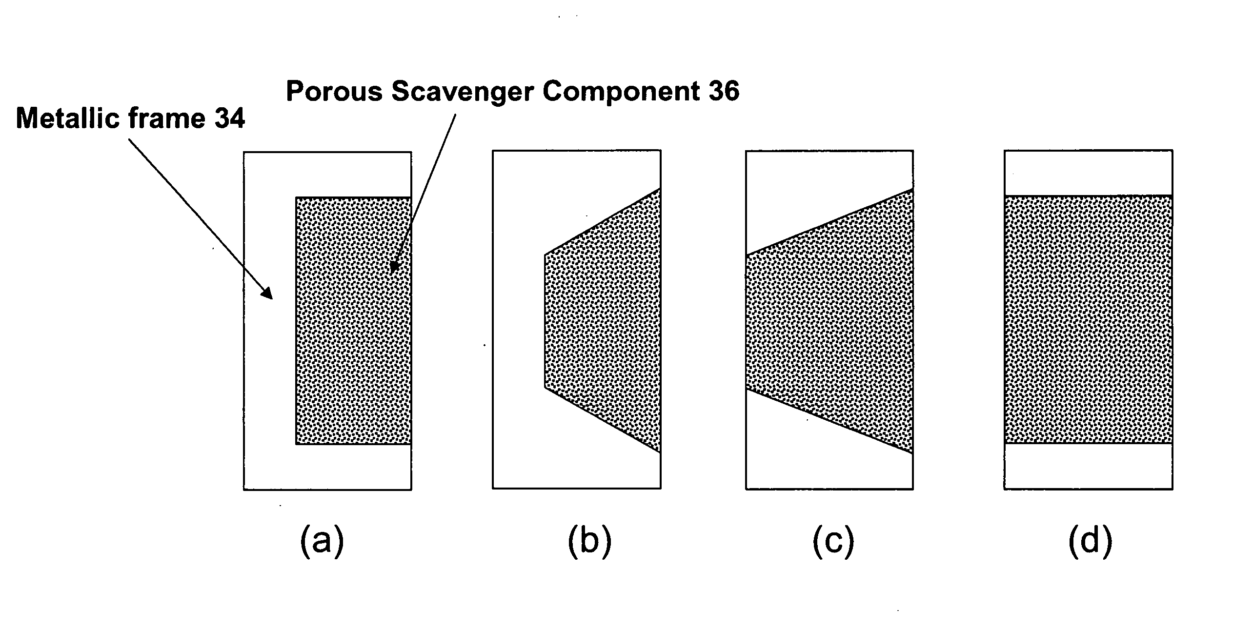
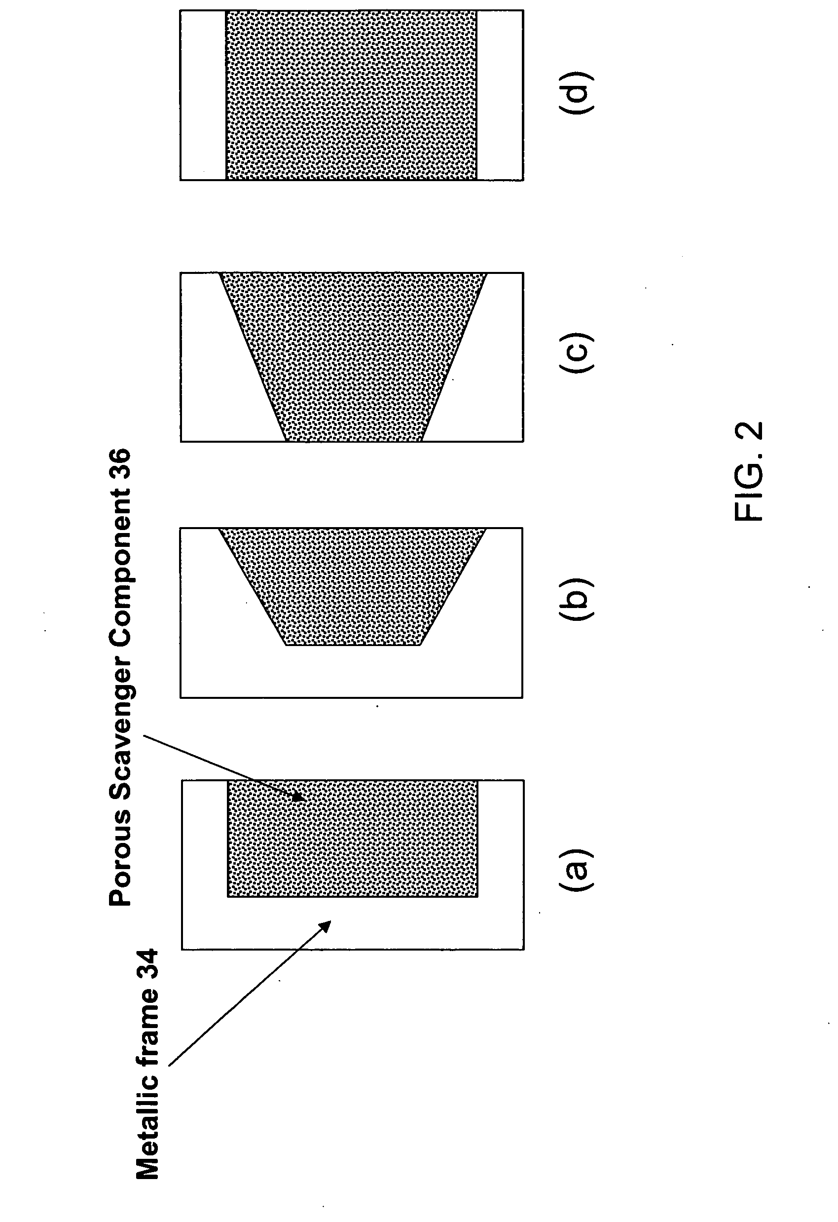
[0066] The following detailed description is an example of a composite pellicle frame configuration incorporating a through-machined window in each of its four sides, each window having a stepped shape and screwed flanges to hold a scavenger component in place. Such a pellicle frame is depicted in FIG. 2(d) and FIG. 4.

[0067] The machined metallic skeleton is formed from a standard metal pellicle frame. The type of frame (part number) is selected by the mask manufacturer based on the size of the reticle. The frame advantageously can have a black anodized finish. In constructing this embodiment of a pellicle frame, the windows preferably are machined prior to any such surface treatment.

[0068] As shown in FIG. 6, a window is machined into each of the pellicle frame's four side walls. The size of each window is determined with two objectives in mind: (1) retaining sufficient mechanical properties of the metallic frame; and (2) maximizing t...

example 2

Processing of Scavenger Components by Sol-Gel Process

[0070] In this example, a sol-gel process is used to prepare a silica scavenger component. In this process, a sol is prepared using hydrolyzed silicon alkoxide and fine silica particles (fumed silica, e.g., Aerosil OX-50 manufactured by Degussa Corporation, of Parsippany, N.J.), as described in published U.S. Patent Application Publication No. 2002 / 0157419 A1 to Ganguli et al., which is incorporated by reference herein. The wet gel obtained by gelation of this sol then is dried using a sub-critical drying process described in U.S. Pat. No. 5,473,826 to Kirkbir et al. This drying process minimizes shrinkage of the gel and decrease of pore size, and it also prevents cracking of the wet gel, which otherwise can occur during drying. Because the gel does not significantly shrink during drying, large crack-free monolithic porous articles having specified pore structures can be easily obtained.

[0071] In one embodiment of this example o...

example 3

Silica Scavenger Component

[0083] In this example, a sol-gel process is used to prepare a silica scavenger component. A sol was prepared using the method disclosed in Example 2 of U.S. Patent Application Publication No. 2002 / 0157419 A1 to Ganguli et al. This sol was cast into a square mold having inner dimensions of about 26.7 cm×26.7 cm, to a height of about 18 mm. After gelation, the gel was subcritically dried according to techniques disclosed in U.S. Pat. No. 5,473,826 to Kirkbir et al. The dried gel was free of any cracks.

[0084] To perform partial densification of the dry gel, the gel was placed in an electrically heated SiC furnace having a quartz enclosure. First, hydrocarbons and water vapor adsorbed on the dry gel surface were removed by heating the gel in an atmosphere containing about 7% oxygen and about 93% nitrogen. In this step, the gel was first heated from about 20° C. to about 170° C., at a heating rate of about 25° C. / hr, and the gel then was held at about 170° C....


PUM

PropertyMeasurementUnit
thicknessaaaaaaaaaa
pore sizeaaaaaaaaaa
pore sizeaaaaaaaaaa

Abstract

A photomask assembly is disclosed having a photomask substrate and a composite pellicle frame that includes both a metallic frame component and a scavenger component. The metallic frame component has a cross-sectional thickness of at least 100 micrometers in all directions, and the volume percentage of the scavenger component relative to the overall volume of the composite frame is in the range of 0.1 to 95%. The scavenger component has a gas permeability to oxygen or nitrogen greater than about 10 ml·mm / cm2·min·MPa, an average pore size between 0.001 and 10 micrometers, and a pore surface area greater than 10 m2 / g. This configuration enables the pellicle frame to have sufficient strength to withstand stresses encountered during normal use, yet also to have the capability of scavenging impurity molecules from the space adjacent to the photomask substrate. In a separate and independent feature of the invention, the scavenger component comprises at least one metal oxide selected from the group consisting of oxides of aluminum, boron, cerium, cobalt, copper, erbium, hafnium, lanthanum, neodymium, praseodymium, scandium, silicon, titanium, yttrium, zirconium, and mixtures thereof. Preferably, the metal oxide is an oxide of zirconium, yttrium, or mixtures thereof.

Description

CROSS-REFERENCE TO RELATED APPLICATIONS [0001] Priority is claimed from co-pending U.S. Provisional Patent Application Ser. No. 60 / 673,539, filed Apr. 20, 2005, and Ser. No. 60 / 686,527, filed May 31, 2005, which are incorporated herein by reference.BACKGROUND OF THE INVENTION [0002] This invention relates generally to photomask assemblies used in a lithographic process and, more particularly, to photomask assemblies incorporating pellicle frames configured to scavenge harmful chemicals from the pellicle space adjacent to a photomask substrate. [0003] In the semiconductor industry, intricate patterns of electronic chips are generally made using photolithographic processes. These processes utilize photomask assemblies, in combination with laser exposure systems, to transfer patterns onto electronic chips. FIG. 1 shows the components of a conventional photomask assembly 10, including a pellicle 12, a frame 14, antireflective films 16, a liquid coating 18, a photomask substrate 20, moun...

Claims


Application Information

Patent Timeline
Patent Type & Authority Applications(United States)
IPC IPC(8): G03F1/14G03F1/64
CPCG03F1/64Y10T428/24793G03F7/70983G03F7/70933Y10T428/3154Y10T428/31544
Inventor MEYERS, DOUGLASGANGULI, RAHULROBINSON, TROYGUMP, ROBERTCOLBERN, STEVENKIRKBIR, FIKRET
Owner YAZAKI CORP
Why Eureka
Try Eureka