[0023] Conveniently, the jet pump is capable of operating in a condition in which no fuel exhaust is entrained by the primary fuel
stream passing through the jet pump nozzle. This can be achieved in the preferred embodiment of the jet pump, without a shut-off valve in the fuel exhaust recycle line, by providing the nozzle bore with a cross-sectional area that is larger than the cross-sectional area of an inlet to the mixing tube from the entrainment chamber when the valve body is fully retracted from the nozzle bore. This can have substantial
advantage when the fuel cell assembly is purged, since the jet pump can be adjusted to entrain no fuel exhaust when the primary fuel stream is replaced with a purge gas that is non-combustible, such as an
inert gas.
[0024] If one or more of the
fuel cells in the fuel cell assembly breaks or cracks by some means, it is possible for air to pass from the
cathode-side to the anode-side of that cell, leading to anode destruction. Such anode destruction is limited to the broken or cracked cell or cells when there is no recycle of the fuel exhaust. However, with fuel exhaust recycle, the air ingress to the fuel exhaust has the potential to contaminate the whole of the fuel side of the fuel cell assembly with
oxygen. Generally, the
oxygen contamination will be identified before the contaminated fuel exhaust is recycled with the primary fuel stream. However, a fuel-side purge will still contaminate the fuel-side with oxygen if contaminated fuel exhaust is entrained in the purge gas. Setting the jet pump so as to entrain no fuel exhaust alleviates the risk of fuel-side
contamination.
[0025] Advantageously, in such a purge, fuel exhaust in the exhaust recycle line between the fuel cell assembly and the jet pump is purged by passing purge gas from the jet pump through the exhaust recycle line to an exhaust
discharge outlet. In an embodiment in which the fuel exhaust recycle line is branched from a fuel exhaust line extending from the fuel cell assembly and delivers to the jet pump only the volume of fuel exhaust to be entrained, the motive purge gas can be directed both through the fuel cell assembly and in reverse flow along the fuel exhaust recycle line when the jet pump is set to entrain no fuel exhaust. This arrangement can reduce the
resonance time of the purge function and can reduce the quantity of gas required for a purge.
[0027] The feature of the recycle line delivering all of the exhaust to the jet pump and the jet pump having an exhaust outlet from the entrainment chamber for
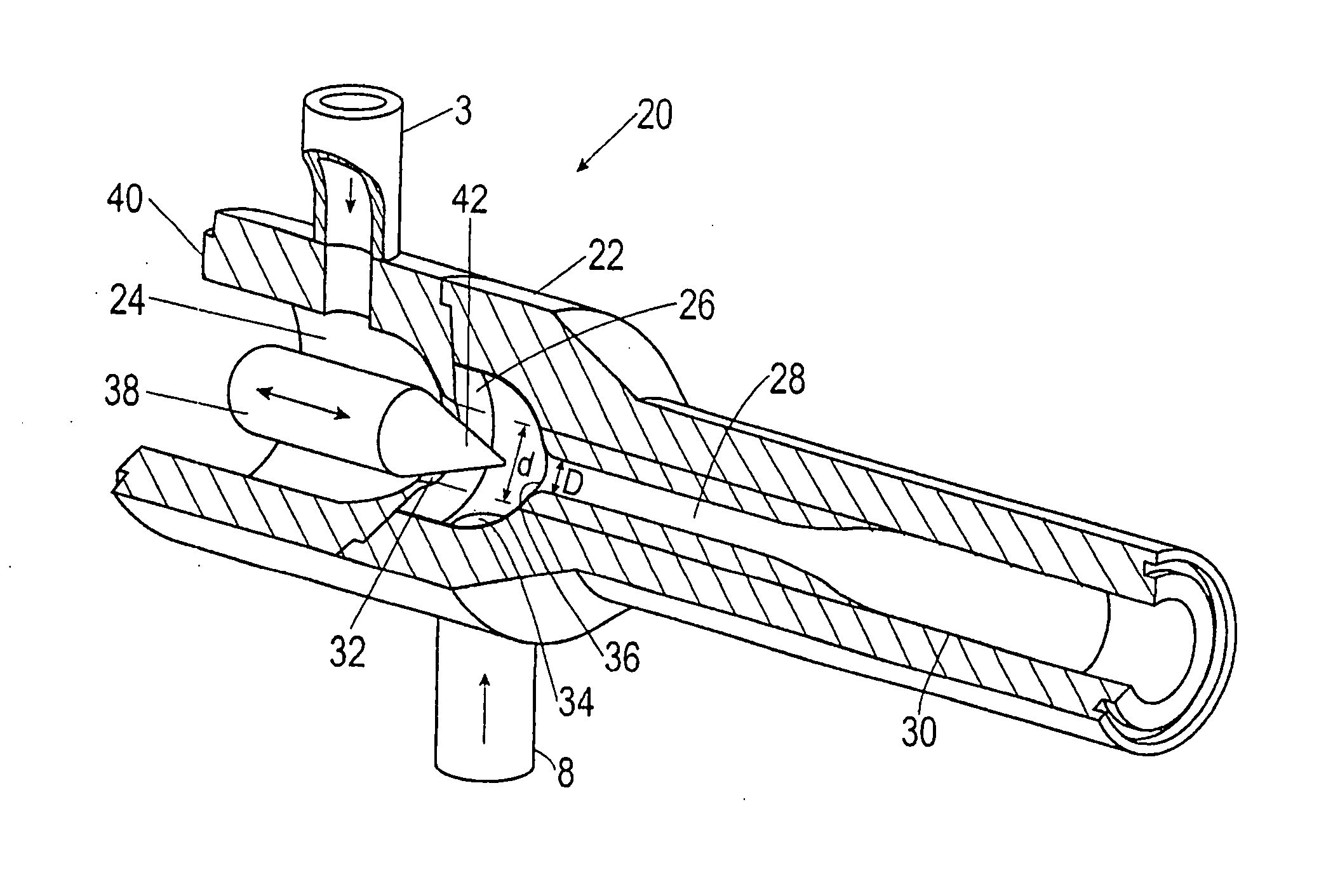
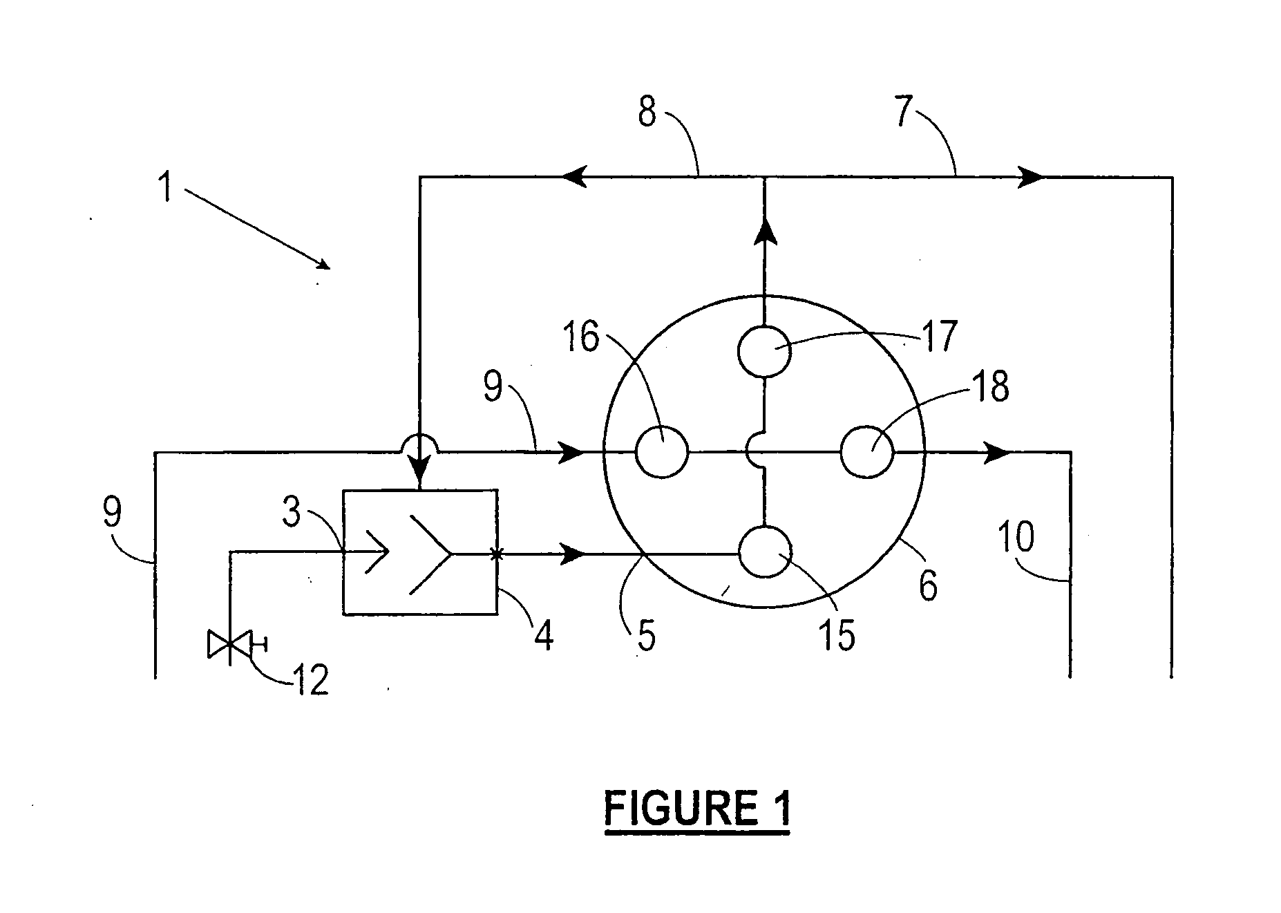
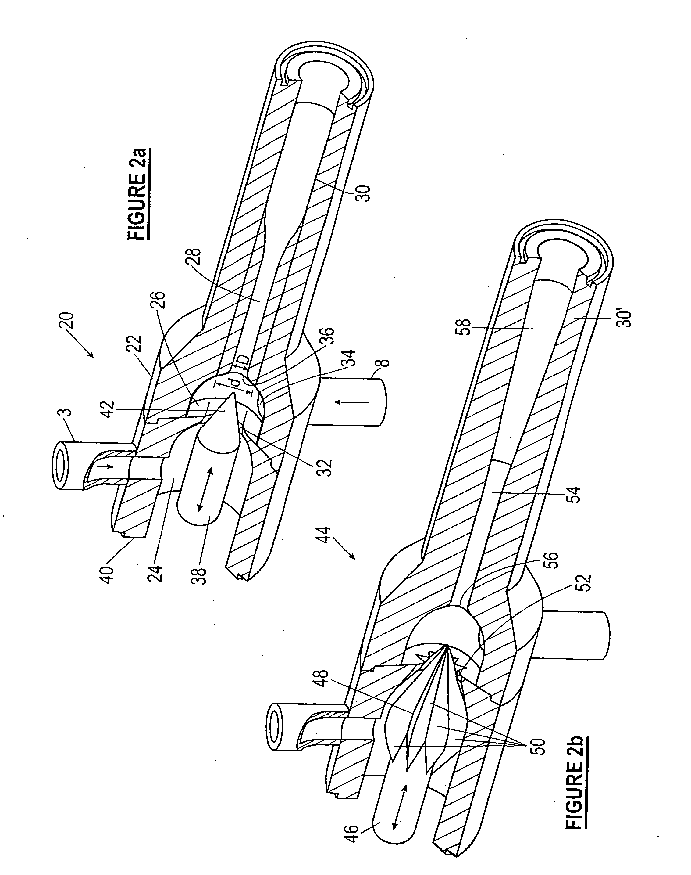
discharge of excess exhaust has application to other exhaust recycle systems than fuel cell systems and is advantageous since recycling all of the exhaust directly through the entrainment chamber is simpler in construction than known recirculation systems. According to this aspect of the invention, there is provided a system for recycling exhaust, including an assembly for generating exhaust from a fuel, a primary fuel line to the assembly, a jet pump in the primary fuel line and adapted to be driven by the flow of primary fuel, a fuel exhaust recycle line from the assembly opening to an entrainment chamber of the jet pump for supply of all of the fuel exhaust from the assembly thereto, and an exhaust
discharge outlet from the entrainment chamber, wherein a nozzle of the jet pump has an adjustable cross-sectional area to provide a variable area flow therefrom of the primary fuel whereby the ratio of fuel exhaust entrained by the primary fuel in the entrainment chamber can be varied, with excess fuel exhaust being discharged through the exhaust discharge outlet.
[0029] In a fuel
cell system, the present invention has
advantage in allowing a variation of the mass flow of recirculated fuel exhaust as a proportion of the primary fuel flow during operation and in allowing the system to operate at a minimal recycle rate during normal operation, yet also allowing good response to ramp up fuel flow and electrical output. When reducing electrical production, and therefore when there is a lower fuel flow requirement, the
variable geometry jet pump will provide higher fuel exhaust recirculation to dilute the primary fuel stream and maintain a desired fuel flow rate to the fuel cell assembly throughout the turndown range. At minimal
power output, the mass fuel flow rate to the fuel cell assembly is therefore enhanced to aid
fuel distribution and permit a much greater turndown range than is otherwise possible. Without this feature, low fuel flow to and poor
fuel distribution within the fuel cell assembly during low
power output operation will eventually produce local
fuel starvation in one or more of the fuel cells and irreversible anode damage as the anode oxidizes. Preferably therefore, the method of the invention comprises adjusting the cross-sectional area of the jet pump nozzle to maintain a selected pressure differential range across the fuel cells in the fuel cell assembly.
[0036] Correspondingly, when the fuel cell system includes a plurality of fuel cell assemblies, each with a respective jet pump for recycling fuel exhaust to the respective assembly, an advantageous method feature of the invention is to individually adjust the cross-sectional area of each jet pump nozzle to vary the cross-section of the primary fuel stream therethrough and thereby independently adjust the ratio of fuel exhaust in the
mixed flow of primary fuel and fuel exhaust delivered to the respective fuel cell assembly.

