Manufacturing method of light-emitting material

a manufacturing method and technology of light-emitting materials, applied in the direction of manufacturing tools, superimposed coating process, liquid/solution decomposition chemical coating, etc., can solve the problems of insufficient volume contraction at such process, insufficient to provide a long-life el display device, and inability to peel, so as to prevent the deterioration of the light-emitting material, not peelable, and not sacrificing luminance.

Inactive Publication Date: 2006-11-16
MORIZANE SHIGERU
View PDF7 Cites 0 Cited by
  • Summary
  • Abstract
  • Description
  • Claims
  • Application Information

AI Technical Summary

Benefits of technology

[0019] This manufacturing method for the light-emitting material forms a thin glass film of a thickness of 0.05 μm or less, which is strong, not peelable by a scratch or the like and not sacrificing luminance in an EL display, forming the film while maintaining a normal temperature range on the light-emitting material, so as to completely seal the surface of the light-emitting material, thereby completely blocking out oxygen, water (moisture) and fine particles, and provides the particular advantage of preventing the deterioration of the light-emitting material, thereby providing a light-emitting material of a long service life capable of maintaining a high luminance.

Problems solved by technology

Difficulties in attaining these targets arise from various causes such as deterioration in the light-emitting material, the electron transport material, the positive hole transport material, the structure of elements, an interface or an electrode.
Also a method of evaporating an inorganic film, for example by sputtering, on the surface of the light-emitting material is being used, but, in this method, the film is merely vapor deposited on the surface and cannot enter small pores, thus being unable to provide a sufficient sealing effect and insufficient to provide a long-life EL display device.
However, all the known technologies for forming such glass coating film requires a heat treatment step at a temperature as high as 1500-2300° C. Also a recently developed sol-gel method of hydrolyzing an organic silicon compound requires a heating process of 1100° C. or higher for glass formation to achieve final complete dehydration, and also a volume contraction at such process is not negligible.

Method used


Image

  • Manufacturing method of light-emitting material
  • Manufacturing method of light-emitting material
  • Manufacturing method of light-emitting material

Examples


example 1

[0042] Formation of glass film having moisture and gas barrier property on fine particles of light-emitting material

[0043] A main reactant (containing a catalyst) was prepared in the following manner.

[0044] 1. 20 g of an organic silicon compound (trade name: “Powder Processing Silicone”, manufactured by Toshiba Silicones Co., with a chemical structure 4 and with physical properties shown in Table 1) were dissolved in 200 ml of ethyl alcohol;

[0045] 2. 0.4 g of boric acid (H3BO3) were added to and mixed with thus obtained solution; 3. 0.4 g of ammonium hydrogen fluoride (NH4F·HF) were added and mixed thereto;

[0046] 4. 1 g of tetrabutyl titanate [(C4H9)4TiO4] was further added and mixed.

TABLE 1Appearancecolorless transparent liquidDynamic viscosity (25° C.)3.7 cstSpecific gravity (25° C.)1.06Refractive index (nD)1.3829Flash point52° C.

[0047] A process utilizing a dispersion medium was conducted in the following procedure.

[0048] At first 200 g of fine particles of a light-emittin...

example 2

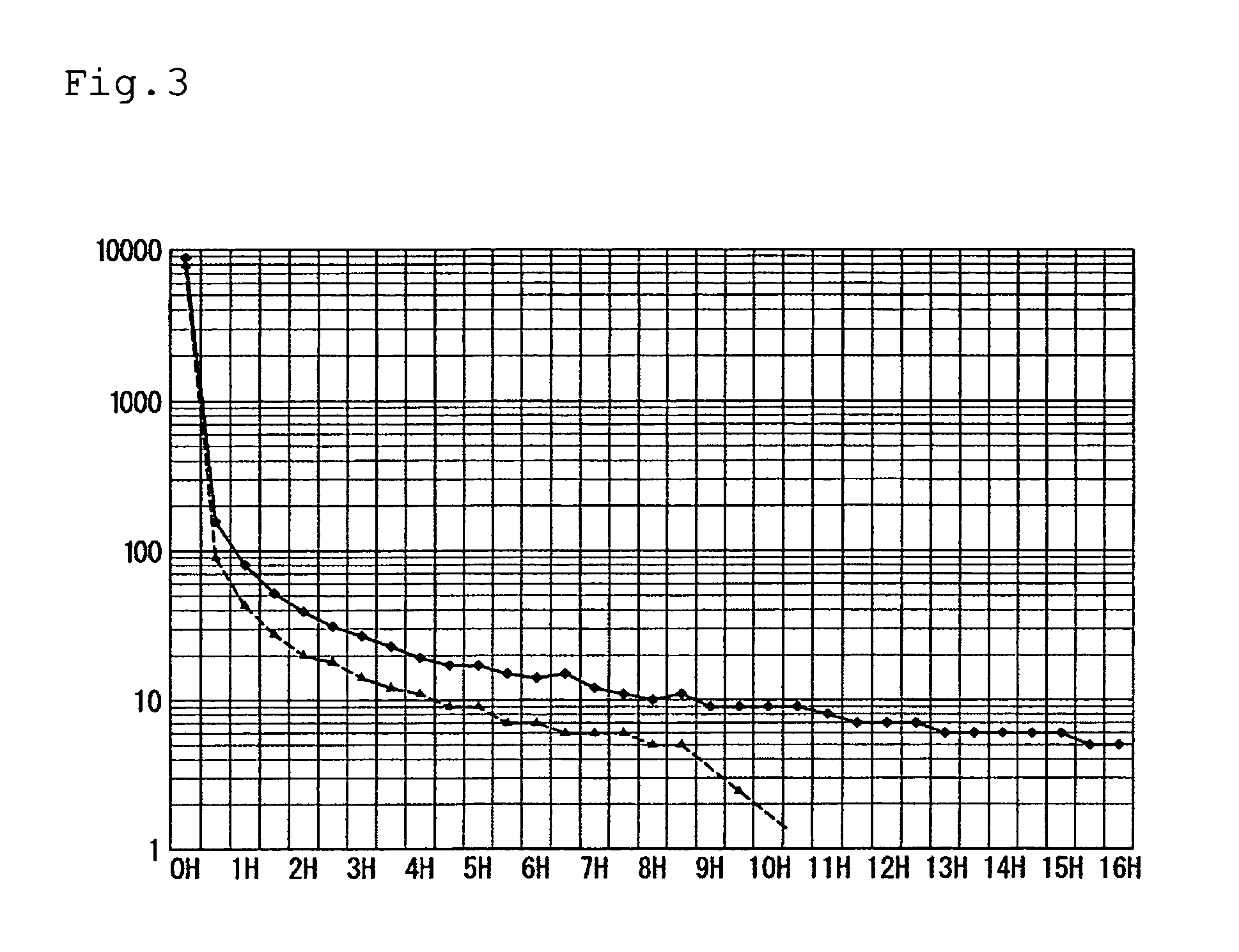
[0055] Fine particles of a phosphor-based phosphorescent material (green, 60 μm, manufactured by Ecran Ltd.) were processed in the identical manner as in Example 1 to obtain particles coated with a glass film of the invention on the surface, and such particles and particles of the same material which were not thus processed were compared with regard to change with time of the luminance of afterglow when irradiated with 4 black lamps of 20 W for 30 minutes. Results are shown in FIG. 3. The measurement was conducted with an equipment LS-100 manufactured by Minolta Co., at a measuring distance of 100 cm and at a vertical measuring angle. In FIG. 3, the light-accumulating material subjected to the glass film forming process (♦) had an afterglow luminance of 5 mcd (millicandela) / m2 even after 16 hours, while the unprocessed same material (▴) showed a rapid decrease in the afterglow luminance after 8 hours.

[0056] As explained above, the manufacturing method of the invention for the light...


PUM

PropertyMeasurementUnit
temperatureaaaaaaaaaa

Abstract

The present invention provides a manufacturing method of a light-emitting material of a long service life, which includes adding boron ions and halogen ions in this order to an alcohol solution of an organic silicon compound having a hydroxyl group and a methoxyl group to obtain a solution of a reaction product by hydrolysis/dehydration condensation at normal temperature, then dispersing fine particles of a light-emitting material in alcohol under agitation, adding the solution of the reaction product into such alcohol dropwise to form a glass film of the reaction product on the surface of the fine particles of the light-emitting material, then separating the fine particles and spray drying the fine particles at a temperature of 200° C. or lower.

Description

BACKGROUND OF THE INVENTION [0001] 1. Field of the Invention [0002] The present invention relates to a manufacturing method of a light-emitting material, capable of maintaining luminance of a light-emitting element such as an EL element, a fluorescent element or a light-accumulating element, thereby achieving long service life thereof. [0003] 2. Description of Related Art [0004] Electroluminescence (hereinafter represented as EL), discovered 1936 by G. Destriau, France, as a phenomenon of light emission when an AC high voltage was applied to a ZnS phosphor, has been an object of numerous developmental researches for application to a flat panel display and is now reaching a stage of commercial use. In the course of such development, a higher luminance, a higher definition, a lower electric power consumption, a longer service life and a lower cost are set as technical targets to be attained. Difficulties in attaining these targets arise from various causes such as deterioration in the...

Claims


Application Information

Patent Timeline
Patent Type & Authority Applications(United States)
IPC IPC(8): B05D5/12B05D7/00
CPCC09K11/02C09K11/08
Inventor MORIZANE, SHIGERU
Owner MORIZANE SHIGERU
Why Eureka
Try Eureka