Multi-layer coating system and method

a coating system and multi-layer technology, applied in the field of multi-layer coating system and method, can solve the problems of mechanical or thermal injury, failure of implanted devices, preventing the acquisition of useful mr images,

Inactive Publication Date: 2006-11-23
ISOFLUX
View PDF11 Cites 39 Cited by
  • Summary
  • Abstract
  • Description
  • Claims
  • Application Information

AI Technical Summary

Problems solved by technology

It must be noted, however, that the presence of a ferromagnetic foreign body (say, shell fragments) in the patient, or a metallic implant (like surgical prostheses, or pacemakers) can present a (relative or absolute) contraindication towards MRI scanning: interaction of the magnetic and radiofrequency fields with such an object can lead to mechanical or thermal injury, or failure of an implanted device.
Even if implanted medical devices pose no danger to the patient, they may prevent a useful MR image from being obtained, due to their perturbation of the static, gradient and / or radio frequency pulsed magnetic fields and / or the response signal from the imaged tissue.
U.S. Pat. No. 6,712,844 states “While researching heart problems, it was found that all the currently used metal stents distorted the magnetic resonance images.
As a result, it was impossible to study the blood flow in the stents which were placed inside blood vessels and the area directly around the stents for determining tissue response to different stents in the heart region.” U.S. Pat. No. 6,712,844 goes on to state “It was found that metal of the stents distorted the magnetic resonance images of blood vessels.
The RF pulses are not capable of penetrating the conventional metal stents.
Similarly, if the eddy currents reduce the amplitudes of the radio frequency pulses, the RF pulses will lose their ability to influence the spins of the protons.
The signal-to-noise ratio becomes too low to produce any quality images inside the stent.
But a current considerable factor weighing against the use of magnetic resonance imaging techniques to visualize implanted stents composed of ferromagnetic or electrically conductive materials is the inhibiting effect of such materials.
These materials cause sufficient distortion of the magnetic resonance field to preclude imaging the interior of the stent.
However, the Melzer solution lacks a suitable integration of an LC circuit within the stent.”
Therefore, in order to perform any coating applied to such devices must also be able to undergo similar strains, which presents a significant challenge.

Method used


Image

  • Multi-layer coating system and method
  • Multi-layer coating system and method
  • Multi-layer coating system and method

Examples


Embodiment Construction

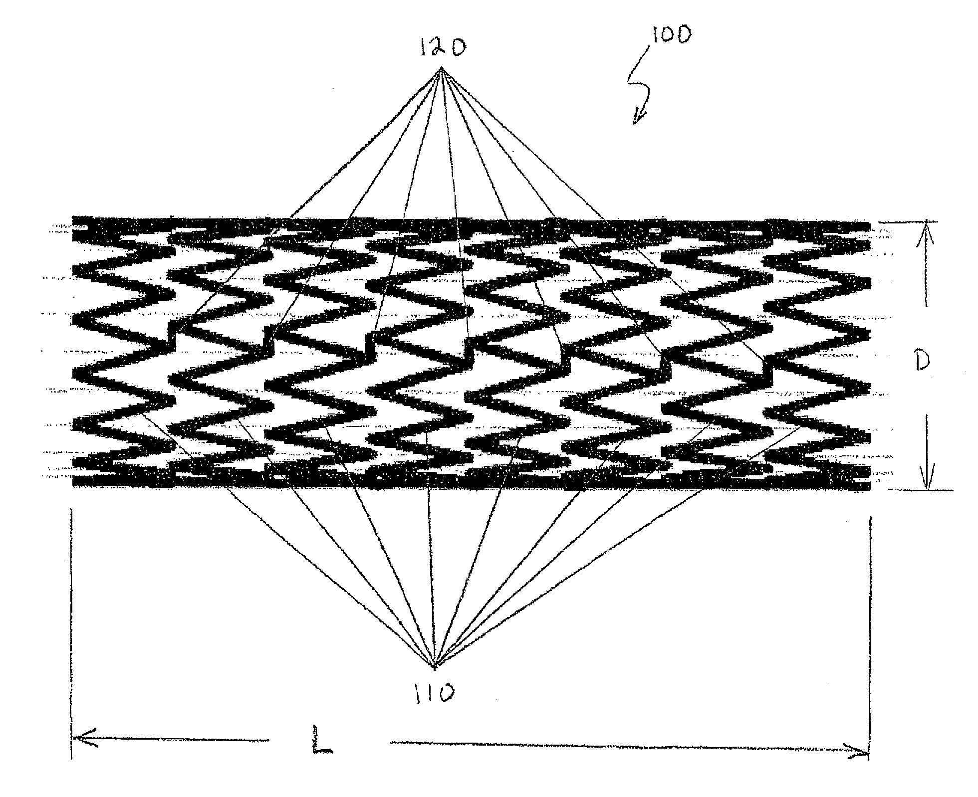
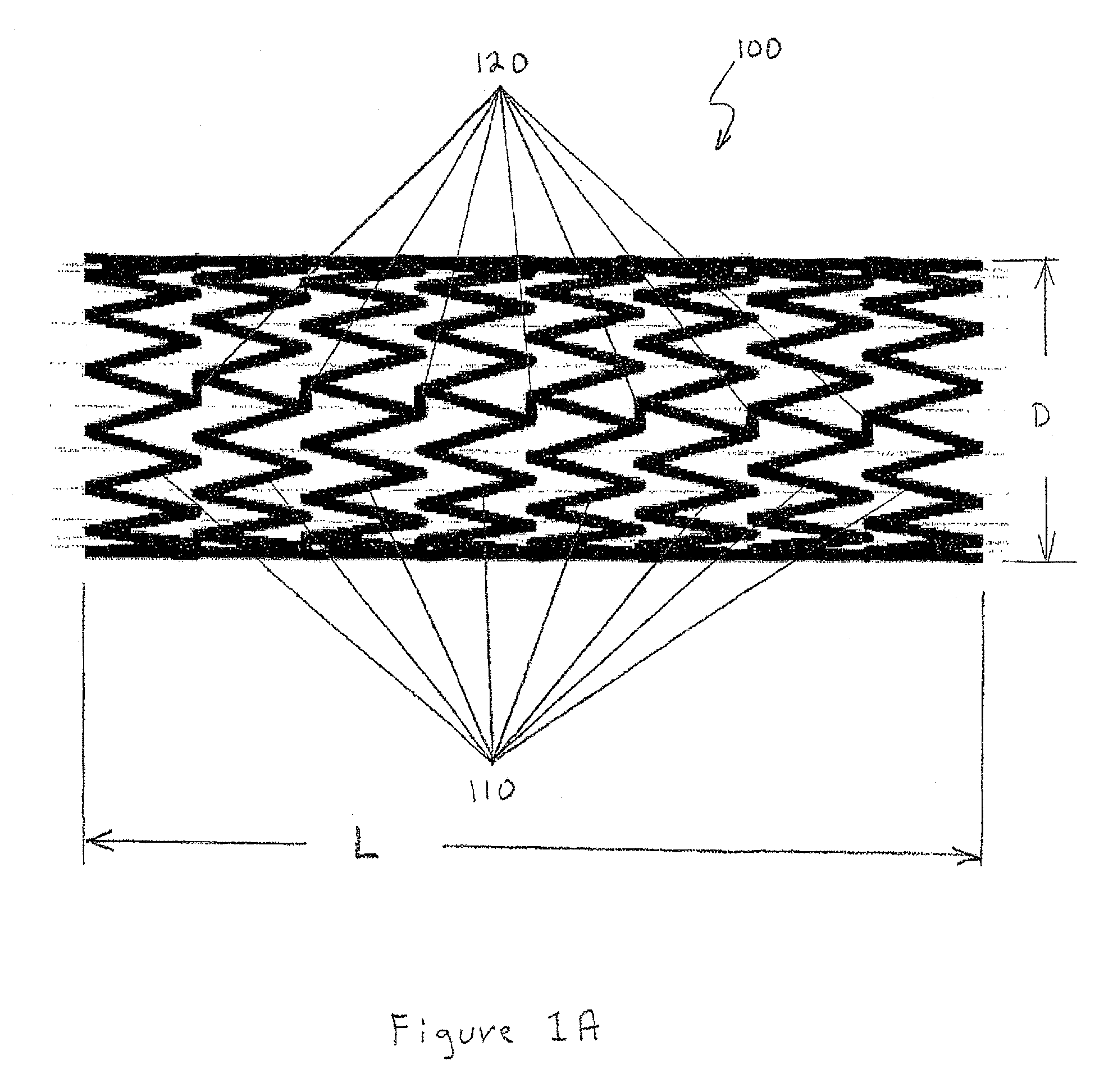
[0028] A stent is an expandable tubular mesh structure that is inserted into a lumen structure of the body to keep it open. Stents are used in diverse structures in the body such as the esophagus, trachea, blood vessels, and the like. Prior to use, a stent is collapsed to a small diameter. When brought into place it is expanded either by using an inflatable balloon or is self-expending due to the elasticity of the material. Once expanded the stent is held in place by its own material strength. Stents are usually inserted by endoscopy or other procedures less invasive than a surgical operation. Stents are typically metallic, for example, stainless steel, alloys of nickel and titanium, or the like and are therefore electrically conducting.

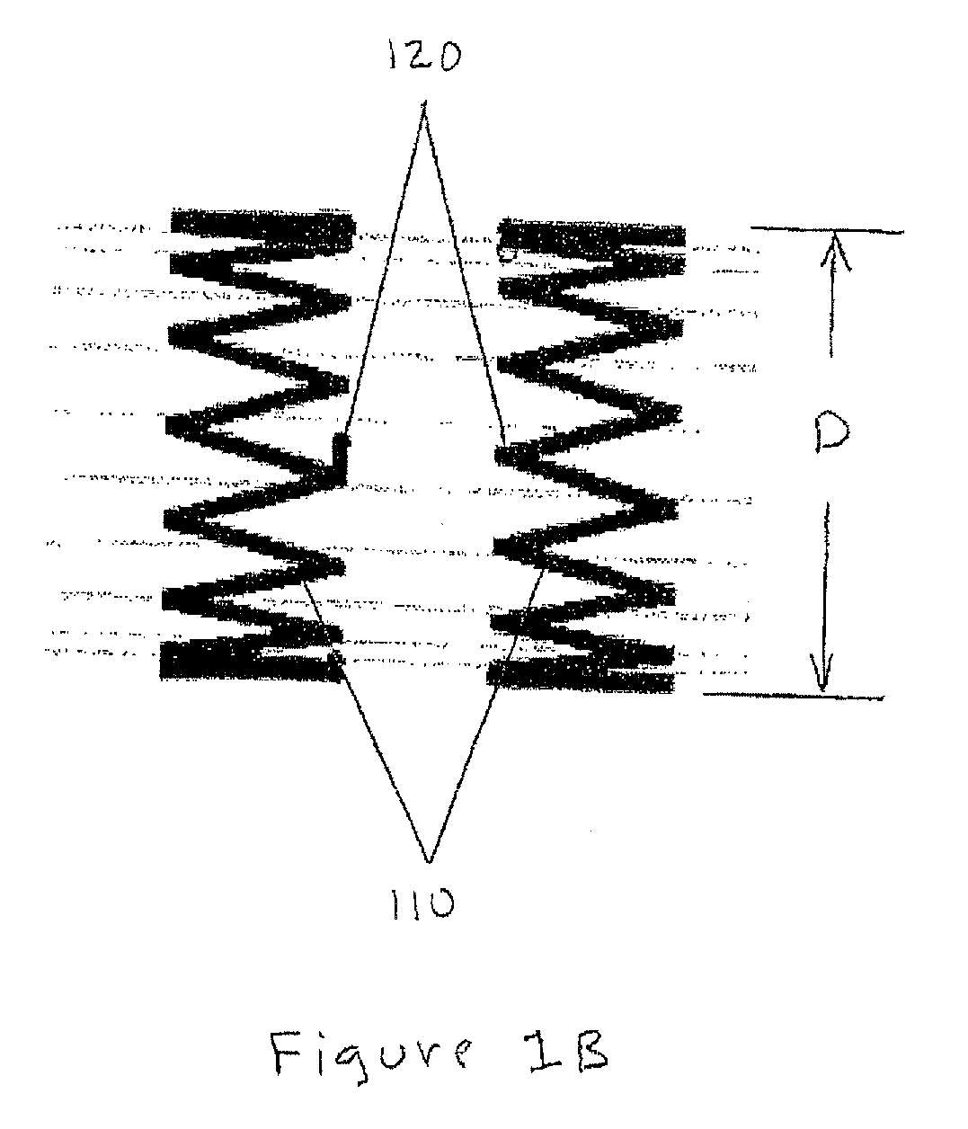
[0029]FIG. 1A is a schematic illustration of one embodiment of a stent to which the invention may be applied. FIG. 1A is a side elevational view of a tubular stent 100 having a length L and a diameter D. Stent 100 is comprised of a plurality of elec...


PUM

PropertyMeasurementUnit
overlap angleaaaaaaaaaa
resonant frequencyaaaaaaaaaa

Abstract

A system and method for coating implantable medical devices so that they do not interfere with MR imaging are described. Using any of the coating processes well known to those skilled in the art, e.g., physical vapor deposition such as evaporation, sputtering, or cathode arc, or chemical vapor deposition, spraying, plasma polymerization, plasma enhanced chemical vapor deposition and the like, multiple sources, including at least one source of an electrically insulating material and at least one source of an electrically conducting material, are oriented and shielded so as to coat separate sections of the implantable medical device. The object being coated is then rotated so that overlapping spiral coatings of the materials from the different coating sources are produced on the object.

Description

CROSS-REFERENCE TO RELATED APPLICATION [0001] This utility patent application claims the benefit of U.S. Provisional Patent Application No. 60 / 682,734, filed on May 19, 2005, the entire disclosure of which is incorporated herein for any and all purposes.BACKGROUND OF THE INVENTION [0002] Magnetic Resonance Imaging (MRI) is extensively used to non-invasively diagnose patient medical problems. The patient is positioned in the aperture of a large annular magnet that produces a strong and static magnetic field. The spins of the atomic nuclei of the patient's tissue molecules are aligned by the strong static magnetic field. Radio frequency pulses are then applied in a plane perpendicular to the static magnetic field lines so as to cause some of the hydrogen nuclei to change alignment. The frequency of the radio wave pulses used is governed by the Larmor Equation. Magnetic field gradients are then applied in 3 orthogonal directions to allow encoding of the position of the atoms. At the en...

Claims


Application Information

Patent Timeline
Patent Type & Authority Applications(United States)
IPC IPC(8): A61L33/00
CPCG01R33/286
Inventor GLOCKER, DAVID A.
Owner ISOFLUX
Why Eureka
Try Eureka