Fluorescence lateral flow immunoassay

a technology of immunoassay and fluorescence, which is applied in the field of fluorescence lateral flow immunoassay, can solve the problems of difficult quantification of visual approaches and limit of visual approaches

Inactive Publication Date: 2006-11-23
BECKMAN COULTER INC
View PDF54 Cites 56 Cited by
  • Summary
  • Abstract
  • Description
  • Claims
  • Application Information

AI Technical Summary

Benefits of technology

[0056] In yet another aspect, the present invention provides a method for extending the analyte detection dynamic range of a lateral flow device for detection of an analyte in a sample fluid, comprising: a high affinity analyte detection particle and a high affinity detection particle, said high affinity analyte detection particle containing means to specifically bind to a first epitope on the analyte with a strong binding force; said high affinity analyte detection particle emitting a first detectable signal; and a low affinity analyte detection particle; said low affinity analyte detection particle containing means to specifically bind to an epitope on the analyte with a weak binding force; said low affinity detection particle emitting a second detectable signal, which may be distinguished from the first detectable signal; a detection zone on said lateral flow device containing means to specifically bind to a second epitope on the analyte, said means being immobilized to avoid migration away from said detection zone; wherein low analyte concentrations are detected by monitoring the binding or non binding of the high affinity detection particle to the detection zone by means of the first detectable signal, and high analyte concentrations are detected by monitoring the binding or non-binding of the low affinity detection particle to the detection zone by means of the second detectable signal.

Problems solved by technology

Although traditional lateral flow immunoassay technology has been oriented towards methods that provide a directly observable visible signal, there are limitations to the visual approach.
Visual approaches are difficult to quantitate, can give results that vary between users (due to the subjective nature of the visual response), and are not sensitive enough to enable the production of certain types of desirable immunoassays, such as highly sensitive whole-blood human chorionic gonadotropin (hCG) or other assays.
In order to comply with modern quality control regulations, such devices also typically contain a number of failsafe sensors and algorithms to detect common user errors, and instruct the microprocessor to return error messages rather than erroneous results, when improper operating conditions are observed.
As a result, the meter can detect application of sample, as well as common error conditions such as insufficient sample.

Method used


Image

  • Fluorescence lateral flow immunoassay
  • Fluorescence lateral flow immunoassay
  • Fluorescence lateral flow immunoassay

Examples


example 1

Construction of Test Strips

[0167] Prototype test strips were constructed using Fusion 5 membrane (Whatman Corporation), 10-mil thick transparent polycarbonate, 10 ml thick white polystyrene, 415 double-sided adhesive (3M corporation), and 1 mil aluminum foil with an adhesive backing.

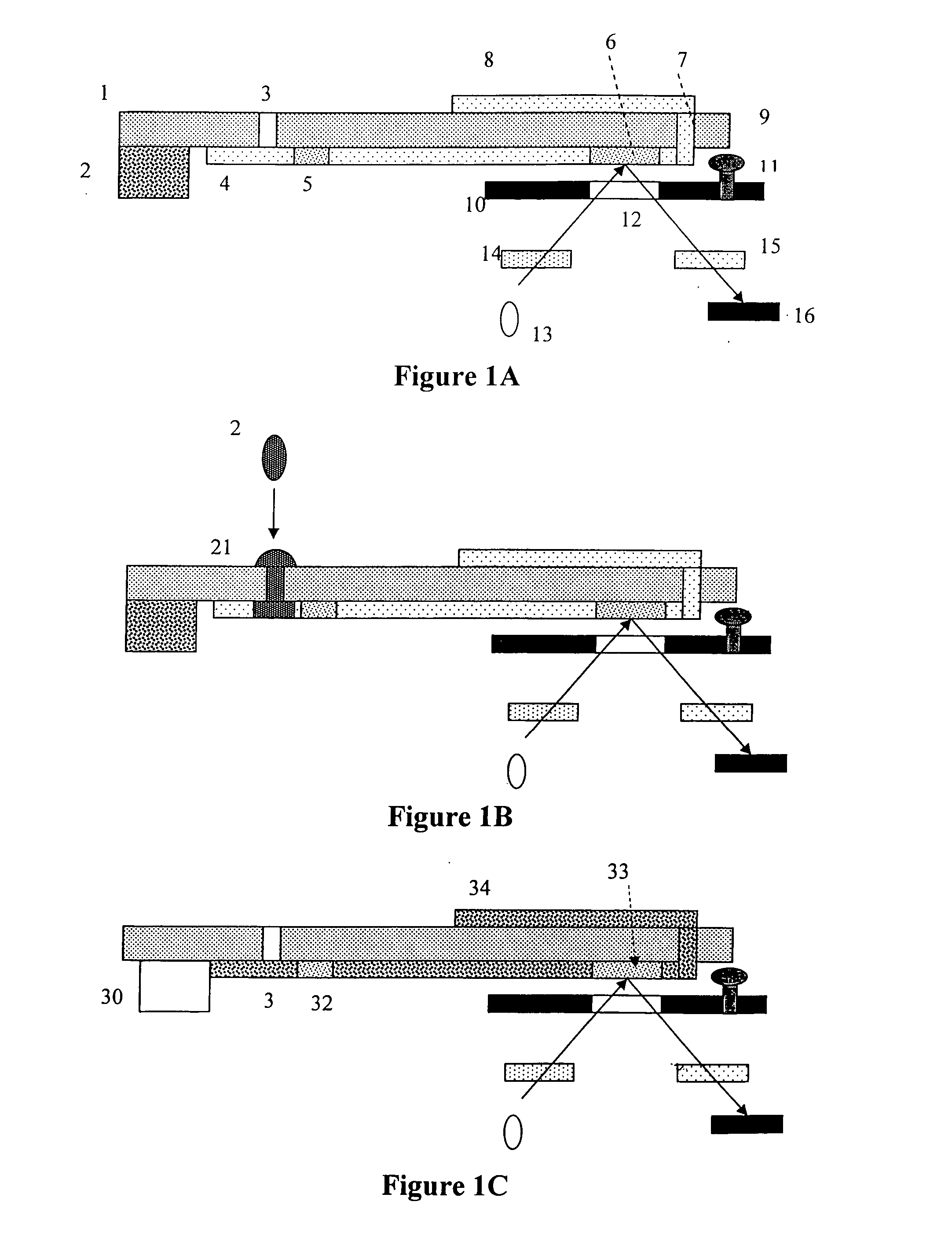
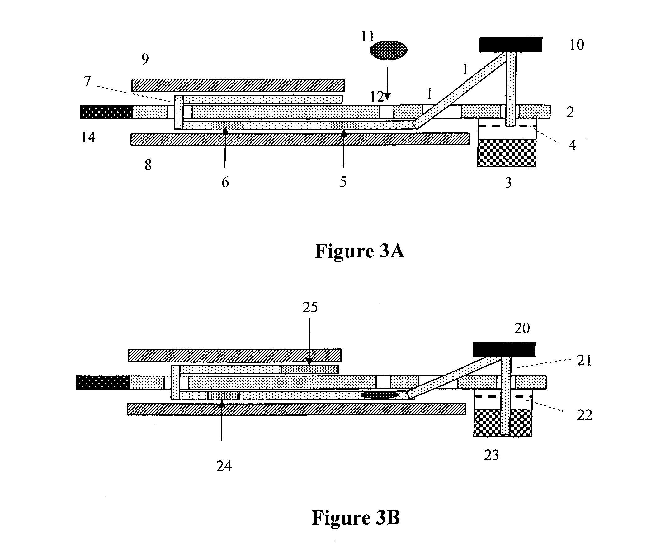
[0168] To construct the device, a 5 / 16″ wide×5 1 / 16″ long piece of Fusion 5 membrane was cut. The sample application zone was located ¾″ from one end. A conjugate storage zone was located 1⅜″ away from the same end. The detection zone was a ¼″ wide zone located 2¼″ away from the same end. A fold, used to bend the Fusion 5 in a 180° turn was located 3 / 16 away from this end. The remainder of the Fusion 5 membrane was used as a wick to remove excess buffer and unbound fluorescent detection particles from the observation zone.

[0169] To hold the test strip, white polystyrene was covered with a layer of 415 adhesive. The styrene strip was ¾″ wide, and 3″ long. A ⅜″ wide slot× 1 / 32″ deep was cut in the cente...

example 2

Dye Migration

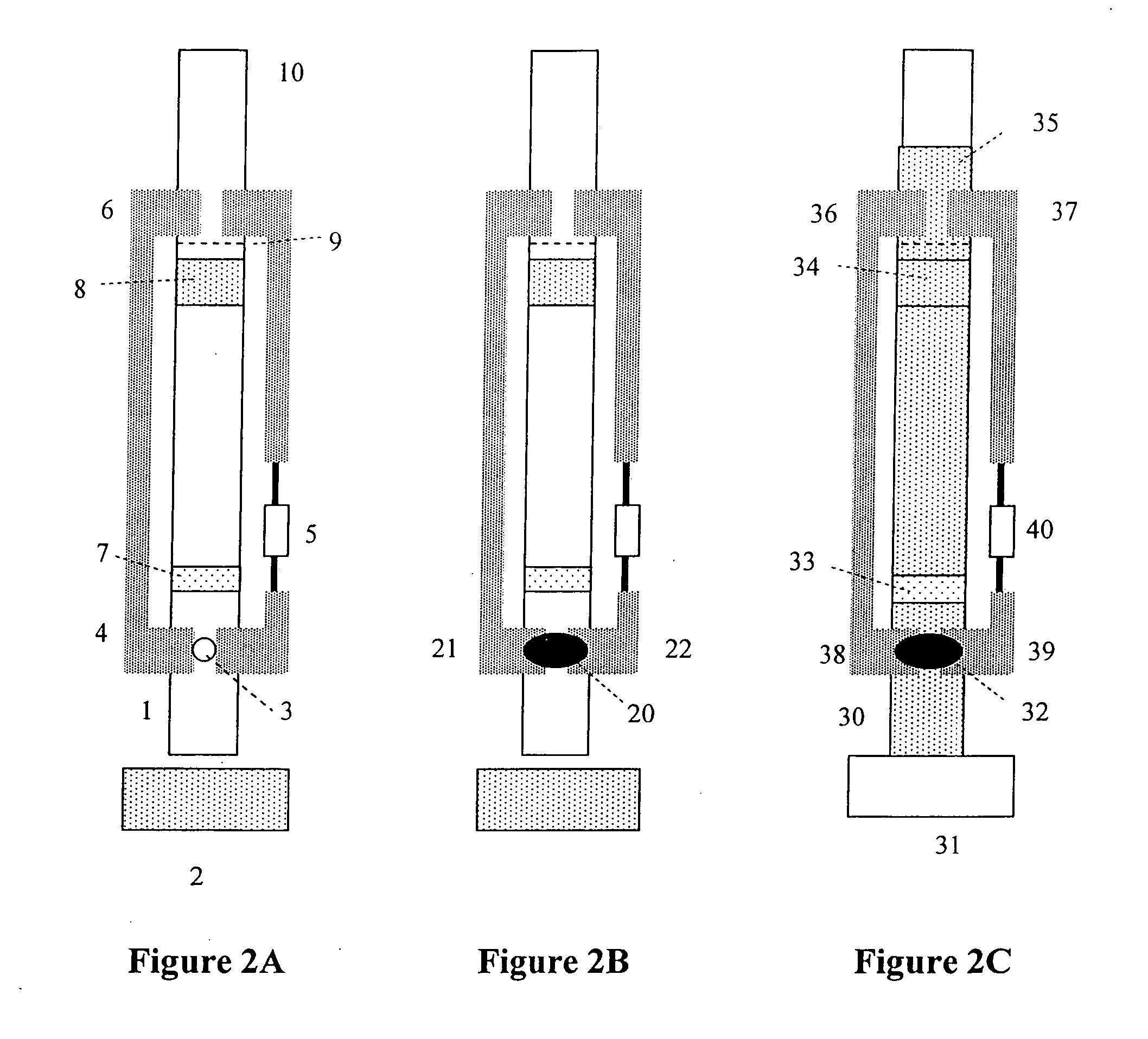
[0174] In this experiment, 5 microliters of a 1 mg / ml solution of Blue dye #1 in water was applied to the conjugate release zone of the test strip, which is located 1⅜″ away from the end of the strip that protrudes slightly out of the plastic sandwich. The blue dye was applied as a thin strip and allowed to dry. After drying, a solution of buffered 0.9% sodium chloride in water was applied to the end of the strip, and dye migration observed. It was seen that the blue dye migrated up to the fold of the strip, and then went through the slot (disappearing from view through the plastic side), and then migrated to the end of the test strip, migrating as a coherent well-defined colored band during this time. The time elapsed from start to completion was about 4 minutes, and about 1 ml of buffer was consumed during this process.

example 3

Electrical Resistance Tests

[0175] Test strips were made as discussed previously, and placed into the combined fluorescence detection and electrical resistance detection optics block described previously. This optics block measured electrical resistance from about 20,000 ohms to about 800,000 ohms, and presented the results as a digitized 12 bit (0-4095) signal in this region. Studies with application of 10-ul whole blood, as well as application of a buffered 0.9% sodium chloride transport buffer, produced a stair step resistance pattern as exemplified in FIG. 4.


PUM

PropertyMeasurementUnit
diameteraaaaaaaaaa
thickaaaaaaaaaa
thickaaaaaaaaaa

Abstract

The present invention relates to devices, kits, instruments and methods for conducting lateral flow assays. A naturally hydrophilic membrane a fluorescent or luminescent label are used in the present devices, kits, instruments and methods. Preferably, a single naturally hydrophilic membrane and/or a fluorescent or luminescent particle label is used.

Description

CROSS-REFERENCE TO RELATED APPLICATIONS [0001] This application claims benefit of U.S. provisional application Ser. No. 60 / 676,019 filed Apr. 29, 2005.FIELD OF THE INVENTION [0002] The present invention relates to devices, kits, instruments and methods for conducting lateral flow assays. A naturally hydrophilic membrane and a fluorescent or luminescent label are used in the present devices, kits, instruments and methods. Preferably, a single naturally hydrophilic membrane and / or a fluorescent or luminescent particle label is used. BACKGROUND OF THE INVENTION [0003] Lateral flow immunoassays are widely used in many different areas of analytical chemistry and medicine. Such assays enable relatively sophisticated chemical analysis to be quickly performed by unskilled users upon complex samples, such as urine, blood, and environmental samples, and typically return results within a few minutes using minimal amounts of additional instrumentation. [0004] Previous lateral flow immunoassays ...

Claims


Application Information

Patent Timeline
Patent Type & Authority Applications(United States)
IPC IPC(8): C12M1/34G01N33/551
CPCB82Y15/00G01N33/5306G01N33/558G01N2333/59G01N33/585G01N33/588G01N33/582G01N33/54388
Inventor ZWEIG, STEPHEN ELIOT
Owner BECKMAN COULTER INC
Why Eureka
Try Eureka