Magnetic recording apparatus using magnetization reversal by spin injection with thermal assistance

a magnetic recording and spin injection technology, applied in the field of high density magnetic recording apparatus, can solve the problems of melting line, increased power consumption, and difficulty in writing to individual magnetic recording bits, and achieve the effect of reducing current density, high density, and effective lowering the coercivity of magnetic recording medium

Inactive Publication Date: 2006-11-30
HITACHI LTD
View PDF0 Cites 25 Cited by
  • Summary
  • Abstract
  • Description
  • Claims
  • Application Information

AI Technical Summary

Benefits of technology

[0011] Accordingly, it is an object of the present invention to provide a high density magnetic recording apparatus capable of performing a magnetic write to a magnetic memory cell therein by directly applying current into the memory cell without using external magnetic field; and performing a record read from the cell structure, characterized in that means of reducing the current density required for the spin-injection magnetization reversal is included.
[0012] With laser light, an element of the magnetic recording medium is heated to a temperature higher than the room temperature but lower than the Curie temperature so as to effectively lower the coerc...

Problems solved by technology

With the progress of magnetic memory cells in miniaturization and integration, this problem becomes more serious, making it very difficult to write to individual magnetic recording bits.
To implement a higher density/capacity HDD or MRAM, increase in the power consumption is therefore inevitable.
In addition, raising the line current may bring about the problem of melting lines.
In the spin-injection magnetization reversal method, however, a large amount of current must be applied.
This not only increases the power consumption but also raise the possibility of lines being degenerated/disabling due to electromigration.
In addition, if the TMR element is used as the magnetic memo...

Method used


Image

  • Magnetic recording apparatus using magnetization reversal by spin injection with thermal assistance
  • Magnetic recording apparatus using magnetization reversal by spin injection with thermal assistance
  • Magnetic recording apparatus using magnetization reversal by spin injection with thermal assistance

Examples


embodiment 1

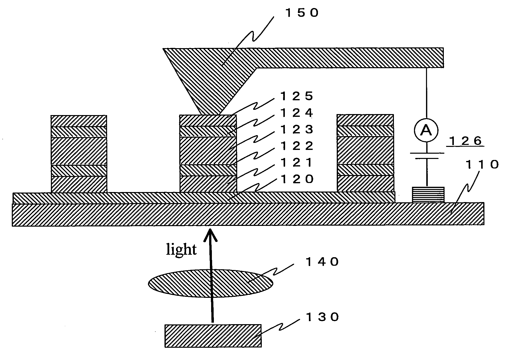
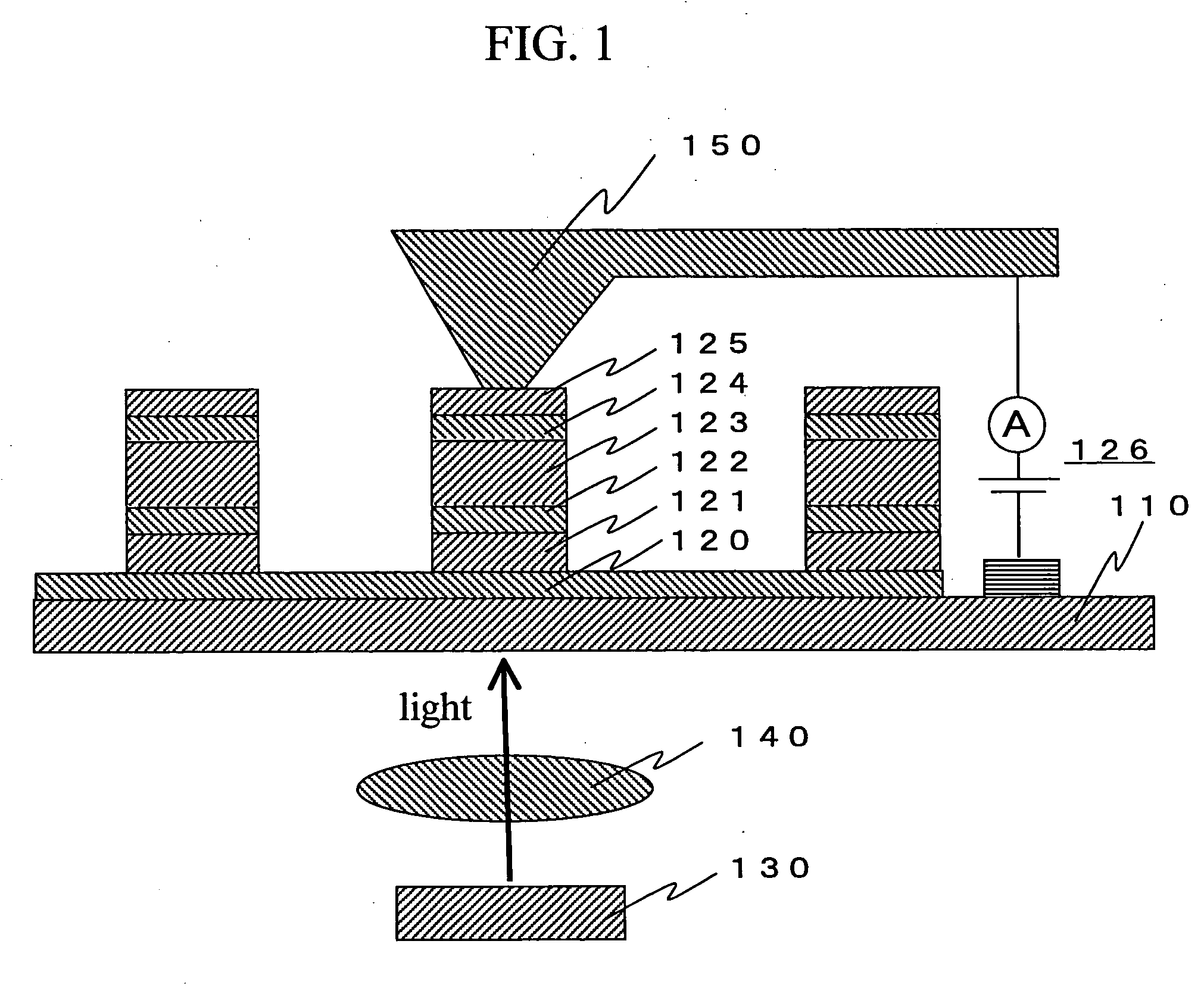
[0021]FIG. 1 (cross section diagram) discloses a first embodiment of the present invention. On an electrode 120 composed of a metal film formed on a surface of a transparent glass substrate 110, a GMR element structure composed of a ferromagnetic metal layer (magnetization free layer) 121, a non-magnetic metal layer 122 and a ferromagnetic layer (magnetization fixed layer) 123 is formed. Further, on the GMR element, an antiferromagnetic metal layer (magnetization pinning layer) 124 to pin the magnetic orientation of the ferromagnetic layer 123 and a metal electrode 125 are formed. The layers 121 through 123 function as one magnetic memory cell. A magnetic recording apparatus has many such magnetic memory cells arrayed on the substrate. If the coercivity of the magnetization fixed layer 123 is enough large to stably maintain its magnetic orientation, the magnetization pinning layer 124 is not necessarily required.

[0022] Toward the back side of the above-mentioned substrate 110, a se...

embodiment 2

[0031]FIG. 3 (cross section diagram) discloses a second embodiment of the present invention. On an electrode 320 formed on a surface of a transparent glass substrate 310, a GMR element structure composed of a ferromagnetic metal layer (magnetization free layer) 321, a non-magnetic metal layer 322 and a ferromagnetic layer (magnetization fixed layer) 323 is formed. Further, on the GMR element, an antiferromagnetic metal layer (magnetization pinning layer) 324 to pin the magnetic orientation of the ferromagnetic layer 123 and a metal electrode 325 are formed. The layers 321 through 323 function as one magnetic memory cell. A magnetic recording apparatus has many such magnetic memory cells arrayed on the substrate. If the coercivity of the magnetization fixed layer 323 is enough large to stably retain its magnetic orientation, the magnetization pinning layer 324 is not necessarily required.

[0032] Toward the back side of the above-mentioned substrate, a semiconductor laser 330 and an o...

embodiment 3

[0037]FIG. 5 (cross section diagram) discloses a third embodiment of the present invention. On an electrode 420 formed on a surface of a non-magnetic substrate 410, an antiferromagnetic metal layer (magnetization pinning layer) 421, a trilayer GMR element structure composed of a ferromagnetic metal layer (magnetization fixed layer) 422, a non-magnetic metal layer 423 and a ferromagnetic layer (magnetization free layer) 424, and then a metal electrode 425 are formed. The layers 422 through 424 function as one magnetic memory cell. A magnetic recording apparatus has many such magnetic memory cells arrayed on the substrate. If the coercivity of the magnetization fixed layer is enough large to stably retain its magnetic orientation, the magnetization pinning layer 421 is not necessarily required.

[0038] With reference to FIG. 5, means to supply a current to a magnetic memory cell while heating it is described below. A probe-shaped optical fiber (hereinafter denoted as the probe) 430 has...


PUM


Abstract

The present invention provides a high density magnetic recording apparatus capable of performing a magnetic write to a magnetic memory cell therein by directly applying current into the memory cell without using external magnetic field; and performing a record read from the cell structure. To reduce the current density required for magnetization reversal by spin injection, the magnetic recording medium is irradiated with laser light so as to heat a magnetic memory cell to a temperature higher than the room temperature but lower than the Curie temperature. While the coercivity of the magnetic recording medium is effectively lowered, magnetic write operation is performed by applying external current into the magnetic memory cell.

Description

CLAIM OF PRIORITY [0001] The present application claims priority from Japanese Application JP2005-151771 filed on May 25, 2005, the content of which is hereby incorporated by reference into this application. FIELD OF THE INVENTION [0002] The present invention relates to a high density magnetic recording apparatus where the magnetic recording cell uses a magnetoresistive effect element having a sandwich stack structure composed of a ferromagnetic layer, a nonmagnetic layer and a ferromagnetic layer. BACKGROUND OF THE INVENTION [0003] In conventional hard disk drives (HDDs) and magnetic random access memories (MRAMs), magnetic recording or writing is done by external magnetic field reversal. In the external magnetization reversal method, a current is forced to flow along a line disposed near a magnetic recording medium. The magnetic field generated by the current is used as an external magnetic field. A record write operation to a specific magnetic memory cell in the magnetic recordin...

Claims


Application Information

Patent Timeline
IPC IPC(8): G11C11/14
CPCG11B5/82G11B2005/0021G11B2005/0005
Inventor ONOGI, TOSHIYUKISAITOH, KAZUO
Owner HITACHI LTD
Why Eureka
Try Eureka