Planar fuel cell stack and method of fabrication of the same

a fuel cell and stack technology, applied in the field of air breathing fuel cells and fuel cell stacks, can solve the problems of fuel cell not meeting the requirements of low-power battery replacement applications, requiring various auxiliary components and a complicated control system, and reducing the internal contact resistance of the cell, so as to reduce the delamination effect of the cell

Inactive Publication Date: 2006-12-21
UNIV OF CONNECTICUT
View PDF7 Cites 11 Cited by
  • Summary
  • Abstract
  • Description
  • Claims
  • Application Information

AI Technical Summary

Benefits of technology

[0023] To reduce the internal contact resistance of the cell, the GDLs are hot-pressed to the membrane electrode assembly. The edges of the GDL and current collector are dipped into a Nafion® solution to reduce delamination.
[0024] Nafion® a commercially available perfluorinated sulfonic acid ionomer manufactured by E.I. du Pont de Nemours & Co. Nafion® is a copolymer of tetrafluoroethyelen

Problems solved by technology

Typically, the aforementioned type of fuel cell works with forced airflow on the cathode side and forced fuel flow on the anode side, requiring various auxiliary components and a rather complicated control system.
Such a fuel cell does not fit the requirements for low power battery replacement applications.
For these applications, the key challenges are to provide acceptable power output and high-energy efficiency in convenient conditions to the user.
It is well known that a forced air design with an external blower is not an attractive option for

Method used


Image

  • Planar fuel cell stack and method of fabrication of the same
  • Planar fuel cell stack and method of fabrication of the same
  • Planar fuel cell stack and method of fabrication of the same

Examples


Embodiment Construction

[0044] It is to be understood that the system and method of the present invention may be advantageously employed without the incorporation of each of the features disclosed herein. It is to be further understood that modifications and variations may be utilized without departure from the spirit and scope of this inventive system and method, as those skilled in the art will readily understand. Such modifications and variations are considered to be within the purview and scope of the appended claims and their equivalents.

[0045] Single Cell Fabrication

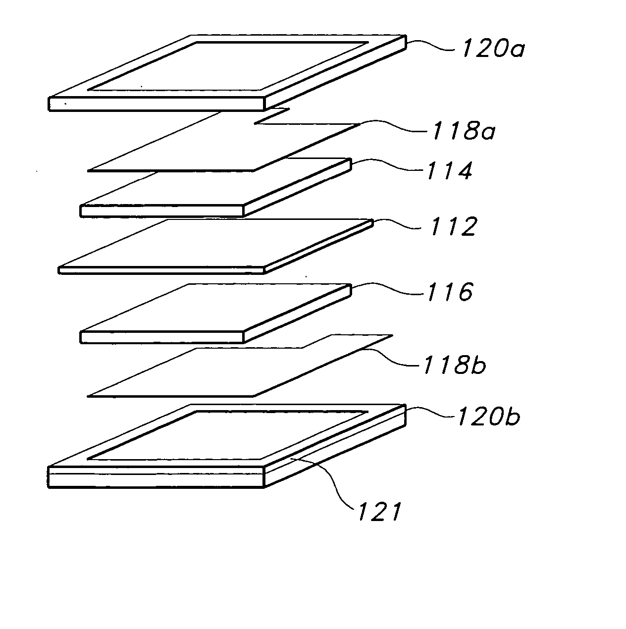
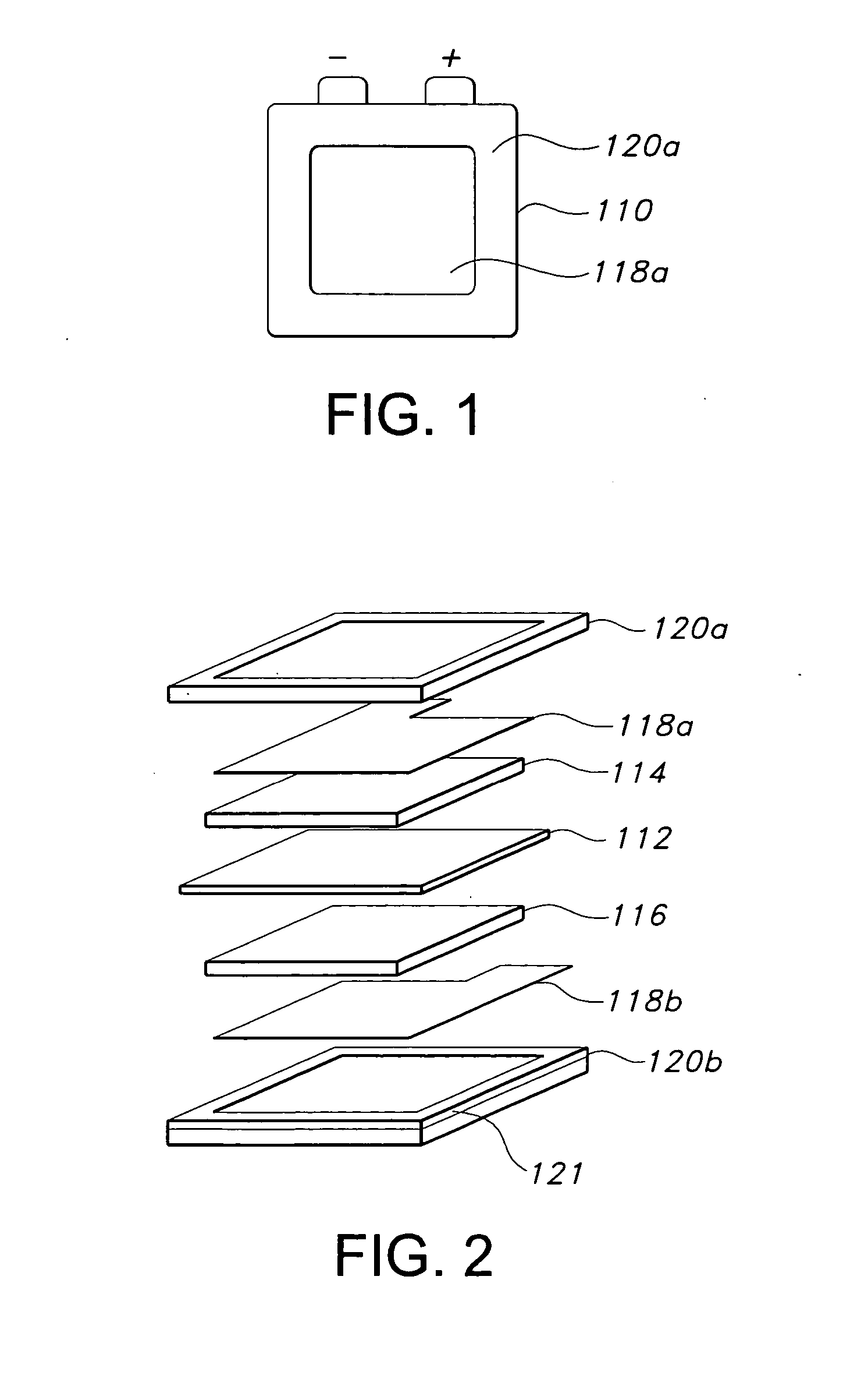
[0046] As shown in FIGS. 1 and 2, a single cell 110 constructed in accordance with the present invention includes a membrane 112 disposed in between an anode 114 and a cathode 116. The opposing side of anode 114 is adjacent a metal mesh current collector 118a and the opposing side of cathode 116 is adjacent a metal mesh current collector 118b. Preferably, anode 114 and cathode 116 comprise catalyst and / or backing layers and GDLs, which ...


PUM

PropertyMeasurementUnit
Temperatureaaaaaaaaaa
Fractionaaaaaaaaaa
Fractionaaaaaaaaaa

Abstract

The present invention provides a system and method for forming an air breathing fuel cell that includes an air permeable cathode layer positioned to be in contact with atmospheric air and an electrically conductive, fuel permeable anode backing layer positioned to be in contact with a mixture of fuel and water, wherein the anode and cathode layers are divided by a pre-swollen electrolyte membrane, and the anode and cathode layers are in contact with electrical current collecting members. The present invention also provides a fuel cell stack consisting of fuel cells of the present invention arranged in a grid-like format within a support frame that is configured to provide electrical connections between the fuel cells.

Description

BACKGROUND OF THE INVENTION [0001] 1. Field of the Invention [0002] The present invention relates to electrochemical fuel cells, and in particular, an air breathing fuel cell and fuel cell stack along with methods for forming the same. [0003] 2. Brief Description of the Related Art [0004] A fuel cell is an electrochemical energy conversion device that transfers the chemical energy in the fuel directly into electric energy. Unlike conventional power devices such as gas turbines, steam turbines and internal combustion engines based on certain thermal cycles, the maximum efficiency of fuel cells is not limited by the Carnot cycle principle. [0005] In a fuel cell electrons are released from the oxidation of fuel at the anode, protons (or ions) pass through an electrolyte, and the electrons are required for reduction of an oxidant at the cathode. The desired output is the largest flow of electrons over the highest electrical potential. Although other oxidants are theoretically possible, ...

Claims


Application Information

Patent Timeline
IPC IPC(8): H01M4/86H01M4/88
CPCH01M4/8817H01M8/0232H01M8/0245H01M8/0247H01M8/0297H01M8/04089Y10T29/49112H01M8/1097H01M8/2455H01M2250/30Y02B90/18Y02E60/523H01M8/1011Y02B90/10Y02E60/50H01M8/242H01M8/2404H01M8/2418
Inventor FAGHRI, AMIRGUO, ZHEN
Owner UNIV OF CONNECTICUT
Why Eureka
Try Eureka