
Membrane-electrode assembly for solid polymer electrolyte fuel cell

Active Publication Date: 2007-01-18
HONDA MOTOR CO LTD
View PDF1 Cites 13 Cited by
  • Summary
  • Abstract
  • Description
  • Claims
  • Application Information

AI Technical Summary

Benefits of technology

[0014] The present inventors have conducted extensive research in order to solve the problems described above, and have found that the problems may be solved by employing a solid polymer electrolyte membrane, in which a nitrogen-containing heterocyclic aromatic compound is introduced into a polymer having a sulfonic acid group, and thereby enhancing the high-temperature stability of the sulfonic acid group.
[0031] In accordance with the present invention, a solid polymer electrolyte membrane may be provided, in which the sulfonic acid exhibits superior stability at higher temperatures without deteriorating proton conductivity of a polymer having excellent hot water resistance, higher concentrations of sulfonic acid and predominant proton conductivity, by introducing a nitrogen-containing heterocyclic aromatic group into the polymer. Accordingly, when the solid polymer electrolyte membranes are applied to membrane electrode assembly for solid polymer electrolyte fuel cells, electric power can be generated under a wide range of conditions of temperature and humidity, in particular at higher temperatures, and thus output of power generation can be raised significantly. In addition, a sulfonic acid group has higer stability at high temperature, so that fuel cells with much longer battery life can be provided.

Problems solved by technology

However, there are problems with the conventional solid polymer electrolyte membrane formed from a polymer having a sulfonic acid group, in that a reversible elimination reaction is likely to occur on the sulfonic acid group or a cross-linking reaction may progress due to higher temperatures, which tends to decrease proton conductivity or embrittle the membrane, resulting in a possible decrease in the power output of the fuel cell or a shutdown in power generation due to a rupture in the membrane.
In order to reduce the probability of these problems as much as possible, currently, the fuel cell is operated below a certain maximum temperature, which consequently results in a power generation output limit.

Method used


Image

  • Membrane-electrode assembly for solid polymer electrolyte fuel cell
  • Membrane-electrode assembly for solid polymer electrolyte fuel cell
  • Membrane-electrode assembly for solid polymer electrolyte fuel cell

Examples


synthesis example 1

[0151] Synthesis of 2,5-dichloro-4′-(l-imidazolyl)benzophenone

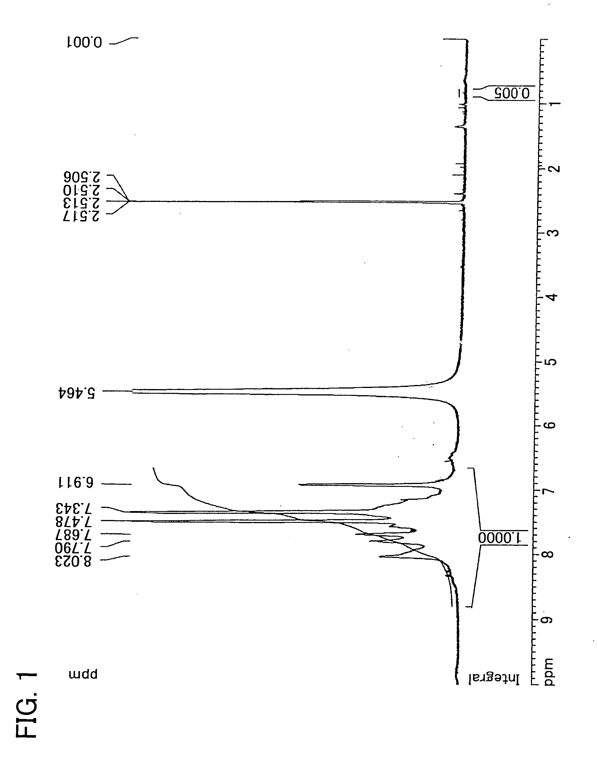
[0152] 150.7 g (0.560 mol) of 2,5-dichloro-4′-fluorobenzophenon, 114.4 g (1.68 mol) of imidazole, 100.6 g (0.728 mol) of potassium carbonate, and 840 ml of N,N′-dimethylacetamide were added into a 2 L three-necked flask equipped with a stirrer, thermometer, cooling pipe, and nitrogen inlet tube. The reaction solution was heated by use of an oil bath and was allowed to react at 110 degrees C. in a nitrogen atmosphere for 2 hours. After the disappearance of material was confirmed by a thin layer chromatography, the mixture was cooled to ambient temperature. Then, the reaction solution was gradually poured into 3 L of water to cause coagulation. The product obtained by filtration was dissolved into 1.2 L of THF, 4 L of toluene was added, and then washed by brine until the water layer becomes neutral. After the organic layer was dried by magnesium sulfate, the solvent was removed by an evaporator. The rough yield was 180 g....

synthesis example 2

[0154] Synthesis of 2,5-dichloro-4′-(1-pyrrolyl)benzophenone

[0155] 134.6 g (0.500 mol) of 2,5-dichloro-4′-fluorobenzophenon, 50.3 g (0.750 mol) of pyrrole, 76.0 g (0.550 mol) of potassium carbonate, and 840 ml of N,N′-dimethylacetamide were added into a 2 L three-necked flask equipped with a stirrer, thermometer, cooling pipe, and nitrogen inlet tube. The reaction solution was heated by use of an oil bath and was allowed to react at 100 degrees C. in a nitrogen atmosphere for 3 hours. After the disappearance of material was confirmed by a thin layer chromatography, the mixture was cooled to ambient temperature. Then, the reaction solution was gradually poured into 3 L of water to cause coagulation. The product obtained by filtration was dissolved into 2.5 L of toluene was added, and then, by using a separating funnel washed by brine until the water layer becomes neutral. After the organic layer was dried by magnesium sulfate, the solvent was removed by an evaporator. The rough yie...

synthesis example 3

[0156] Synthesis of 2,5-dichloro-4′(2-benzothiazolethioxy)benzophenone

[0157] 269.1 g (1.000 mol) of 2,5-dichloro-4′-fluorobenzophenon, 175.6 g (1.050 mol) of 2-benzothiazolethiol, 152.0 g (1.100 mol) of potassium carbonate, and 1.500 ml of N,N′-dimethylacetamide were added into a 3 L three-necked flask equipped with a stirrer, thermometer, cooling pipe, and nitrogen inlet tube, and dehydrated. The reaction solution was heated by use of an oil bath and was allowed to react at 110 degrees C. in a nitrogen atmosphere for 2 hours. After the disappearance of material was confirmed by a thin layer chromatography, the mixture was cooled to ambient temperature. Then, the reaction solution was gradually poured into 3 L of water to cause coagulation. The resulting product by filtration was dissolved into 4 L of toluene. The organic layer was washed by brine to be neutral. After the organic layer was dried by magnesium sulfate, the solvent was removed by an evaporator. The rough yield was 35...


PUM

PropertyMeasurementUnit
Equivalent per massaaaaaaaaaa
Structureaaaaaaaaaa
Molecular weightaaaaaaaaaa

Abstract

A membrane-electrode assembly for solid polymer electrolyte fuel cells, in which a sulfonic acid is an ion exchange group, and the heat resistance is superior, is provided. The membrane-electrode assembly for solid polymer electrolyte fuel cells contains a polymer including a principal chain that forms polyphenylene structure, a branched chain having a sulfonic acid group, and a branched chain having a nitrogen-containing heterocyclic group. It is preferred that a branched chain having a nitrogen-containing heterocyclic group is a structure expressed by the general formula (D) below.

Description

[0001] This application is based on and claims the benefit of priority from Japanese Patent Application No. 2005-206280, filed on 15 Jul. 2005, the content of which is incorporated herein by reference. BACKGROUND OF THE INVENTION [0002] 1. Field of the Invention [0003] The present invention relates to a solid polymer electrolyte membrane which enhances thermostability. In particular, the present invention relates a membrane electrode assembly for solid polymer electrolyte fuel cells having a polymer electrolyte membrane that improves the stability of a sulfonic acid group and power durability at high temperature when the membrane is employed as a proton conductive membrane contained in fuel cells. [0004] 2. Related Art [0005] Fuel cells generate electric power by a process in which hydrogen gas, produced from various hydrocarbon fuels, such as natural gas, methane, and oxygen in the air, are electrochemically reacted to generate electric power directly. Therefore, they have been att...

Claims


Application Information

Patent Timeline
IPC IPC(8): H01M8/10
CPCC08J5/2256C08J2371/12H01M8/1027H01M8/103C08J2381/06H01M8/1039H01M8/1067H01M2300/0082Y02E60/523H01M8/1032Y02E60/50
Inventor KANAOKA, NAGAYUKIIGUCHI, MASARUSOHMA, HIROSHI
Owner HONDA MOTOR CO LTD
Learn More