Liquid crystal display device and manufacturing method thereof

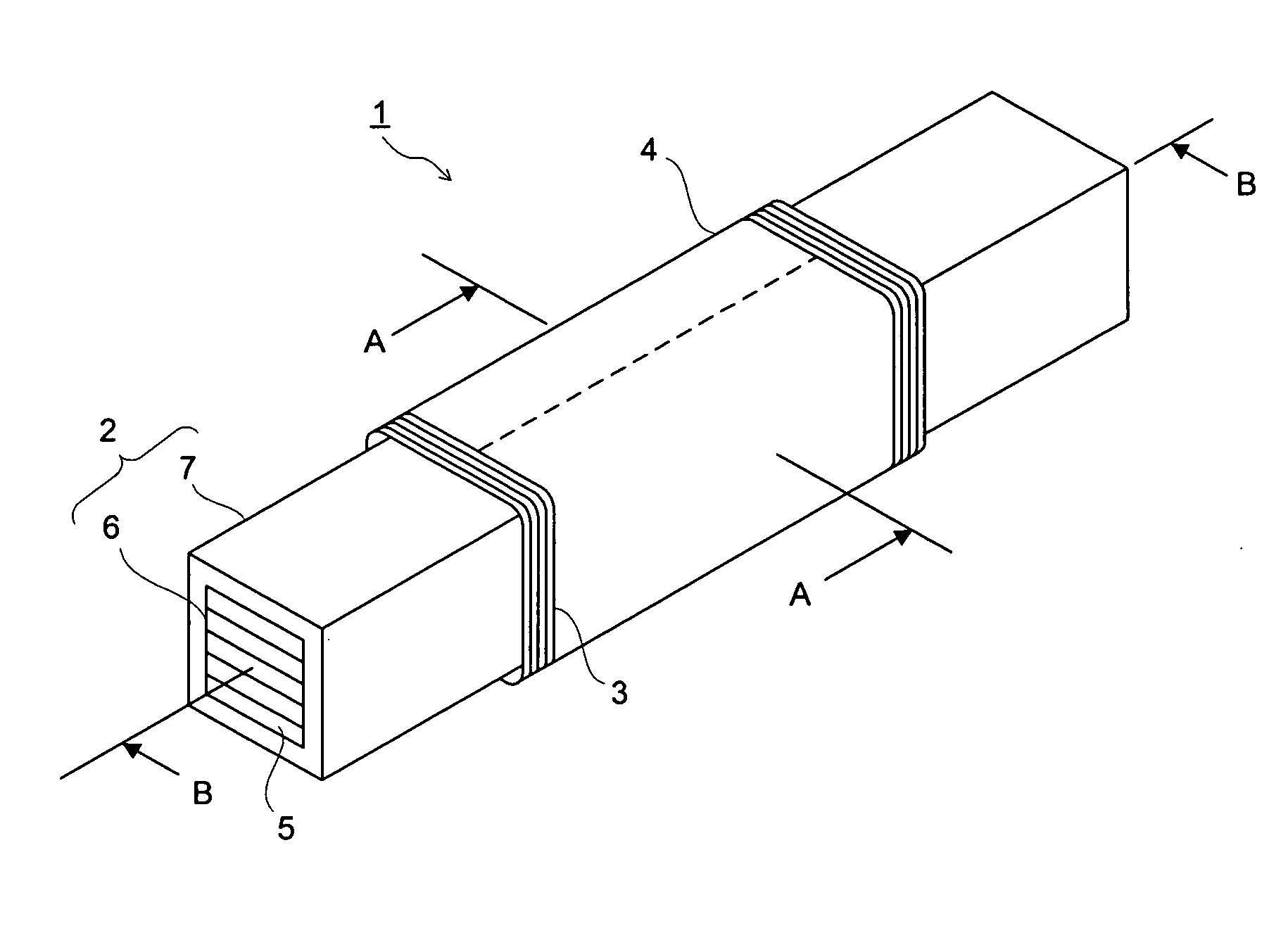
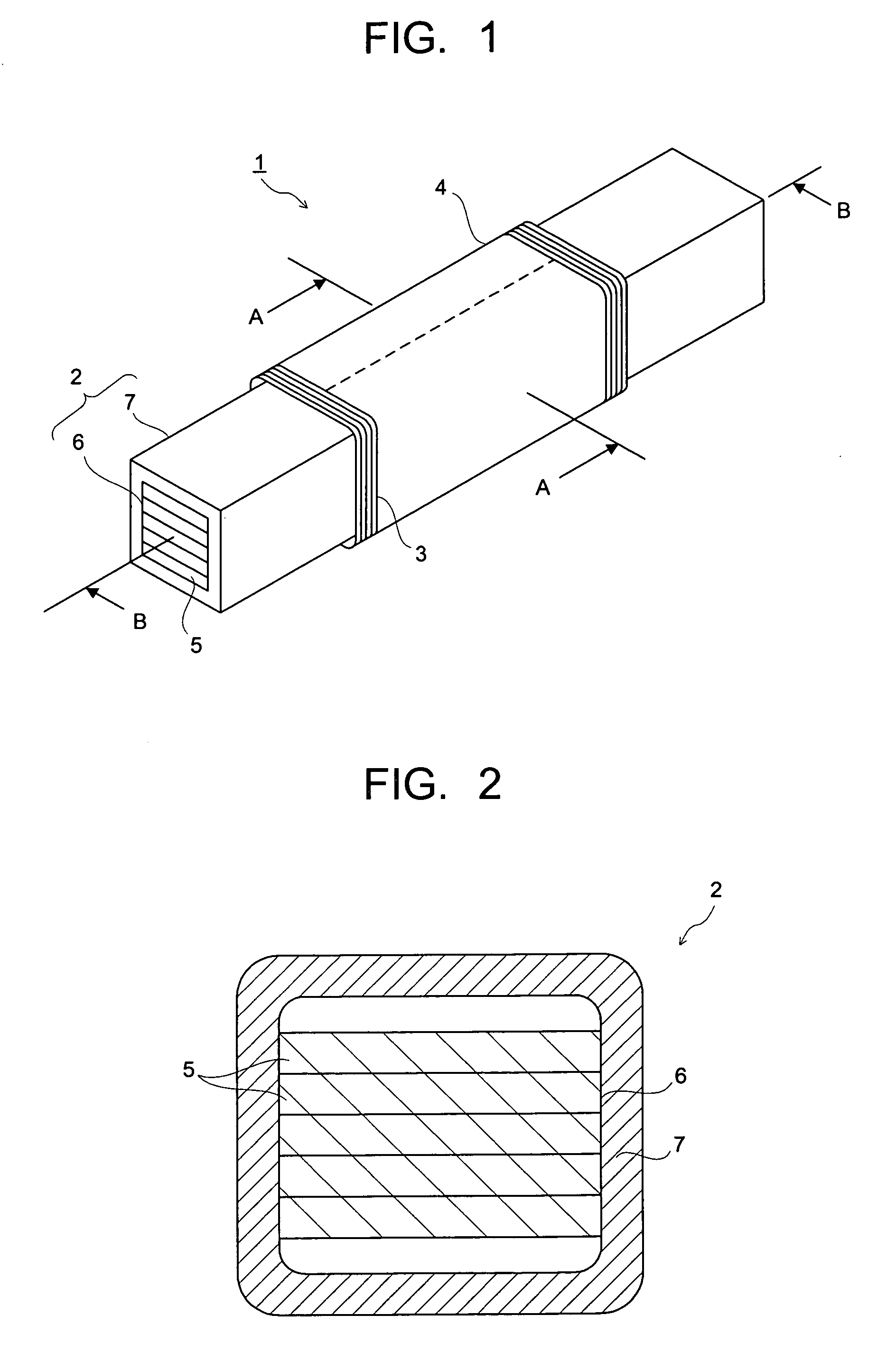
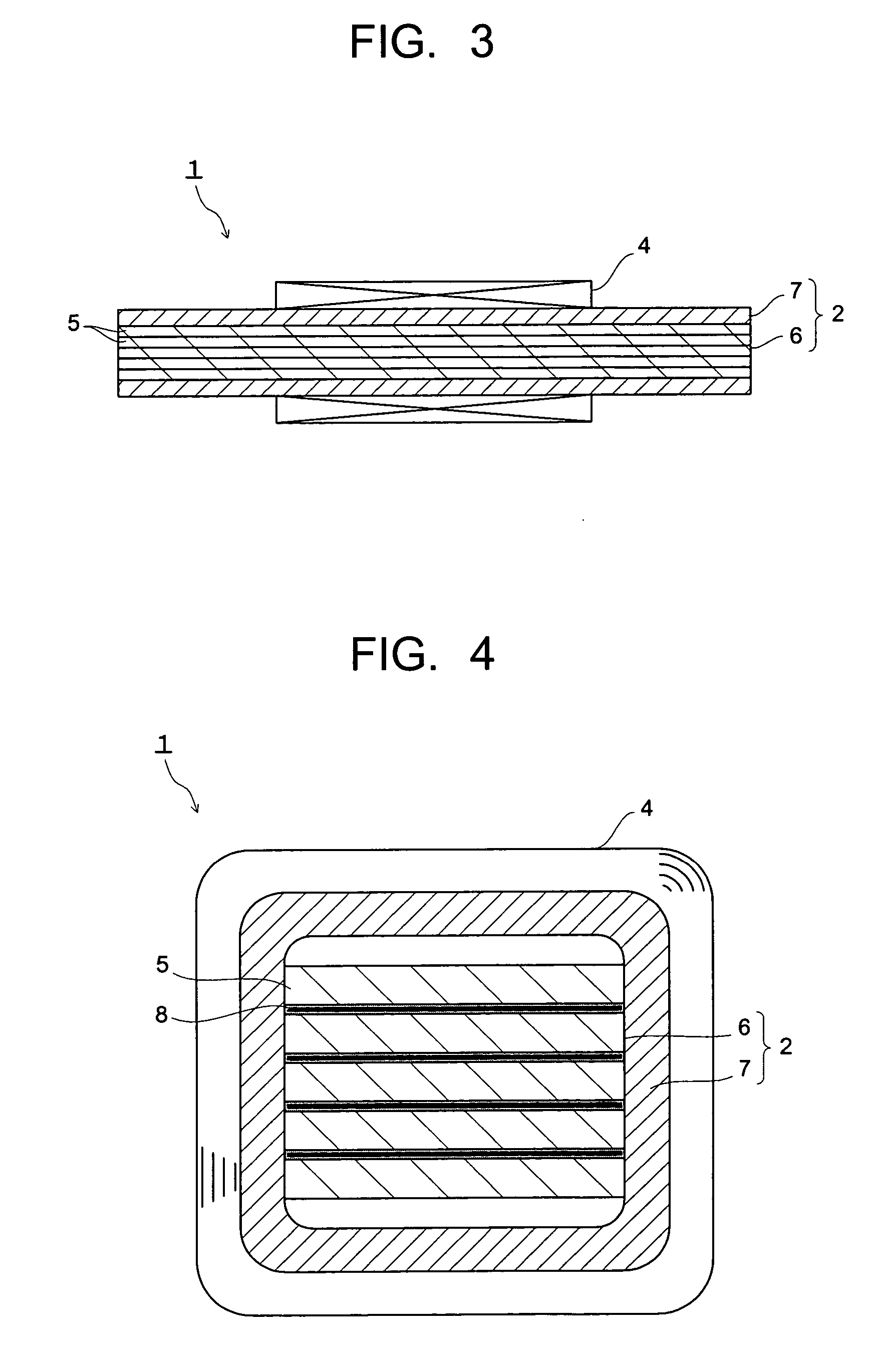
a liquid crystal display device and liquid crystal technology, applied in the direction of transformer/inductance magnetic core, loop antenna with ferromagnetic core, core/yokes, etc., can solve the problems of low magnetic permeability in terms of magnetic characteristics, ferrite core cannot be used for antenna elements, ferrite is brittle, etc., to improve the characteristics of inductance l, reduce the space factor of multilayer body 6, and bendability or the like of the core 2

Active Publication Date: 2007-02-22
KK TOSHIBA +1
View PDF2 Cites 36 Cited by
  • Summary
  • Abstract
  • Description
  • Claims
  • Application Information

AI Technical Summary

Benefits of technology

[0084] The space within the insulating coating layer 7 is preferably filled with the multilayer body 6 in order to enhance the characteristics of the inductance L and the like. But, if the space factor of the multilayer body 6 to the inside space of the insulating coating layer 7 is excessively large, bendability or the like of the core 2 becomes low. Therefore, it is desirable that a space for free deformation of the multilayer body 6 of the magnetic alloy thin ribbons 5 is reserved within the insulating coating layer 7. Specifically, it is desirable that the space factor of the multilayer body 6 to the inside space (e.g., the inner volume of tube) of the insulating coating layer 7 is 90% or less, and more desirably 80% or less.
[0085] It is desirable that the space factor of the multilayer body 6 is 30% or more because the characteristics of the inductor 1 become low if the space factor of the multilayer body 6 is excessively small. As a method of lowering the space factor of the multilayer body 6, it is also effective to configure the multilayer body 6 by stacking, for example, the magnetic alloy thin ribbons 5 each having a different width. The space factor indicates a relative value when a cross-section space factor having the multilayer body 6 filled most densely into the inside space of the insulating coating layer 7 is determined 100.
[0086] Thus, the multilayer body 6 of the magnetic alloy thin ribbons 5 configuring the core 2 is disposed in a free state within the insulating coating layer 7, and the insulating coating layer 7 itself is flexible, so that the core 2 can be bent (e.g., curved) easily. Then, the magnetic alloy thin ribbons 5 in the bent state can be prevented from the occurrence of unwanted distortion or stress. Accordingly, it is possible to suppress the original characteristics (inductance L, Q value and the like) of the inductor 1 from lowering even when the inductor 1 is disposed within a limited space. In other words, various types of equipment in which the inductor 1 is mounted can be made compact and high performance.
[0087] The inductor 1 shown in FIG. 1 to FIG. 3 has the multilayer body 6 which has the plural magnetic alloy thin ribbons 5 stacked in a non-adhered state. Meanwhile, the inductor 1 shown in FIG. 4 has the multilayer body 6 which has the plural magnetic alloy thin ribbons 5 stacked via the flexible insulating adhesive layer 8. FIG. 4 is a transverse sectional view showing a modified example of the inductor 1. Even the multilayer body 6 having the flexible insulating adhesive layer 8 can enhance the bendability of the core 2, and it becomes possible to suppress the occurrence of distortion or stress in the magnetic alloy thin ribbons 5 in the bent state.
[0088] Thus, property degradation when disposed in the bent state can also be suppressed by the inductor 1 which has the flexible insulating adhesive layer 8 applied to the interlayer insulation between the magnetic alloy thin ribbons 5. Accordingly, it becomes possible to conform to the provision of compact and high-performance various types of equipment in which the inductor 1 is mounted. The inductor 1 shown in FIG. 4 has the same structure as that of the inductor 1 shown in FIG. 1 through FIG. 3 except that the multilayer body 6 which has the plural magnetic alloy thin ribbons 5 stacked via the flexible insulating adhesive layer 8 is used. Especially, it is desirable that the space factor of the multilayer body 6 to the inside space of the insulating coating layer 7 is 30% or more and 90% or less.
[0089] It is important that the flexible insulating adhesive layer 8 in the inductor 1 shown in FIG. 4 has good deformability and high electrical isolation than a bonding strength. If the electrical isolation of the adhesive layer 8 is low, there is a possibility that the magnetic alloy thin ribbons 5 contact to one another to increase eddy current. For the insulating adhesive layer 8, it is desirable to use, for example, an elastomer based adhesive agent such as chloroprene rubber based, nitrile rubber based, polysulphide based, butadiene rubber based, SRB based or silicone rubber based, a resin based adhesive agent mainly formed of thermoplastic resin such as vinyl acetate based, polyvinyl alcohol based, polyvinyl acetal based, vinyl chloride based, polystyrene based or polyimide based, or an adhesive agent formed of a mixture of them.

Problems solved by technology

Conventionally, it is general to use ferrite for the core of the antenna element, but the ferrite is brittle and has drawbacks that it is cracked if deformed only slightly and has a low magnetic permeability in terms of the magnetic characteristics.
Therefore, the ferrite core cannot be used for the antenna element which is required to be thin and compact.
Especially, the portable equipment is required to have shock resistance, so that its sufficient miniaturization cannot be achieved by using the ferrite which is easily cracked.
The ferrite also has a disadvantage that a stable temperature characteristic cannot be obtained because it has a low Curie-point of about 200° C.
But, the conventional antenna element, which is configured by winding a coil around the multilayer body (core) of the magnetic alloy thin ribbons, has not provided sufficient characteristics for compactness and high performance demanded to be achieved for the data carrier parts and radio-controlled timepieces.
But, for example, Patent Documents 2 and 3 cannot bend easily because the magnetic thin ribbons are mutually adhered with an insulating resin and the magnetic core has high rigidity.
But, an antenna element using a multilayer body (core) of existing magnetic alloy thin ribbons has not been studied enough about factors influencing on the characteristics when it is made compact and short.
Therefore, characteristics (e.g., inductance L and Q value) conforming to the miniaturization and high performance which are demanded for the data carrier parts and radio-controlled timepieces have not been achieved.
But, when the width of the magnetic alloy thin ribbons is narrowed to realize the miniaturization of the antenna element, an influence of the demagnetizing field cannot be neglected, and there is a possibility that the characteristics of the antenna element are decreased.

Method used


Image

  • Liquid crystal display device and manufacturing method thereof
  • Liquid crystal display device and manufacturing method thereof
  • Liquid crystal display device and manufacturing method thereof

Examples


examples 1 to 5

, REFERENCE EXAMPLE 1 & 2, COMPARATIVE EXAMPLES 1 & 2

[0136] First, 30 amorphous magnetic alloy thin ribbons having an alloy composition of (Co0.90Fe0.05Mn0.02Nb0.03)71Si15B14 and a thickness of 17 μm, a width of 0.8 mm and a length of 50 mm were prepared. The surfaces of the amorphous magnetic alloy thin ribbons were insulated with SiO2, and they were stacked. The multilayer body of the amorphous magnetic alloy thin ribbons was inserted into a silicone resin tube having an outer diameter of 1.5 mm, a thickness of 0.2 mm and a length of 50 mm (Example 1) to produce a core. The multilayer body of the amorphous magnetic alloy thin ribbons was inserted into the same shaped polyethylene resin tube (Example 2), polypropylene resin tube (Example 3), polyamide resin tube (Example 4), and styrene rubber tube (Example 5) to produce cores.

[0137] A phenol resin tube (Reference Example 1) and an epoxy resin tube (Reference Example 2) having the same shape were used to produce the same cores as ...

example 6

[0140] Inductors were produced in the same way as in Example 1 except that amorphous magnetic alloy thin ribbons having different surface roughness Rf were used in Example 1. A ratio (L / L0) of inductance L in a bent state (a bent state so that a distance between ends becomes 20 mm) with respect to inductance L0 in a straight state of the individual inductors, and a ratio (Q / Q0) of Q value (Q) in the bent state with respect to the Q value (Q0) in the linear state were measured and evaluated. The results are shown in Table 3 and FIG. 17.

TABLE 3SurfaceInductanceQ valueSampleroughnessInitialWhenInitialWhenNo.RfL0bent LL / L0Q0bent QQ / Q010.0510.88.90.8328.416.10.5520.1010.711.11.0328.322.20.7630.1810.712.11.1328.723.90.8140.2010.512.01.1428.924.40.8250.2510.412.31.1929.024.80.8360.3010.311.91.1629.124.00.8070.3810.110.61.0529.322.60.7580.459.99.50.9629.521.60.7190.509.58.50.9029.619.20.63100.609.46.50.6929.515.20.50

[0141] It is apparent from Table 3 and FIG. 17 that the surface roughness...

example 7

[0142] Inductors were produced in the same manner as in Example 1 except that the number of stacked layers of the amorphous magnetic alloy thin ribbons in Example 1 was changed to change the space factor in the tube. A ratio (L / L0) of inductance L in a bent state (the same bent state as in Example 6) to inductances L0, L0 of the inductors in a straight state, Q value in the same straight state, and a ratio (Q / Q0) of Q value (Q) in the bent state to Q0 were measured and evaluated. The results are shown in Table 4, FIG. 18 and FIG. 19. FIG. 18 shows changes of L and Q with respect to the space factor when the inductor is in a bent state. FIG. 19 shows changes of L / L0 ratio and Q / Q0 ratio with respect to the space factor.

TABLE 4Magneticalloy thinribbonInductanceQ valueSam-SpaceValueWhenplefactorInitialL perWhenInitialbentNo.Q'ty(%)L0layerbent LL / L0Q0QQ / Q01132.92.93.471.1813.513.30.9925146.41.37.561.1818.117.80.98310297.80.88.941.1520.720.30.98415438.70.310.01.1523.721.50.91520579.30....


PUM

PropertyMeasurementUnit
frequencyaaaaaaaaaa
magnetic domain widthaaaaaaaaaa
frequencyaaaaaaaaaa

Abstract

An inductance element (1) comprises a core (2) having a multilayer body (6) composed of magnetic alloy thin ribbons (5) and an insulating coating layer (7) which covers the peripheral surface of the multilayer body without being bonded thereto, and a coil (4) wound around the core (2). The magnetic alloy thin ribbons (5) are stacked in a non-adhered state or with a flexible insulating adhesive layer therebetween. Having such a structure, the inductance element can stably attain good characteristics even when it is small-sized or made short.

Description

TECHNICAL FIELD [0001] The present invention relates to an inductance element, which is used as an antenna element or the like of various types of equipment for transmitting a signal by a radio wave, and a method for manufacturing the same. BACKGROUND ART [0002] In recent years, a system for transmitting a signal by a radio wave between outside equipment and data carrier parts which are provided with an antenna element and a circuit element for storing data is being used in various fields. As data carrier parts, RF tag (signal frequency: 120 to 140 kHz (typically, 134.2 kHz)), a pen tag (signal frequency: 500 kHz) and noncontact IC card (signal frequency: 13.56-MHz band) are being put into practical use for management of various types of articles, physical distribution management, entering and leaving management, various types of tickets, a car-mounted keyless entry and immobilizer, various types of portable equipment such as portable telephones and the like. [0003] And, a system of...

Claims


Application Information

Patent Timeline
Patent Type & Authority Applications(United States)
IPC IPC(8): H01F27/24H01F3/02H01F17/04H01F27/28H01F27/32H01Q7/06
CPCH01F17/045H01F27/2847H01F27/324H01Q7/06H01F3/04H01F41/0226H01F27/24H01F27/28
Inventor INOUE, TETSUOKUSAKA, TAKAOYAMADA, TAIJU
Owner KK TOSHIBA
Why Eureka
Try Eureka