
Apparatus and method for field-injection electrostatic spray coating of medical devices

Inactive Publication Date: 2007-03-01
BOSTON SCI SCIMED INC
View PDF13 Cites 63 Cited by
  • Summary
  • Abstract
  • Description
  • Claims
  • Application Information

AI Technical Summary

Benefits of technology

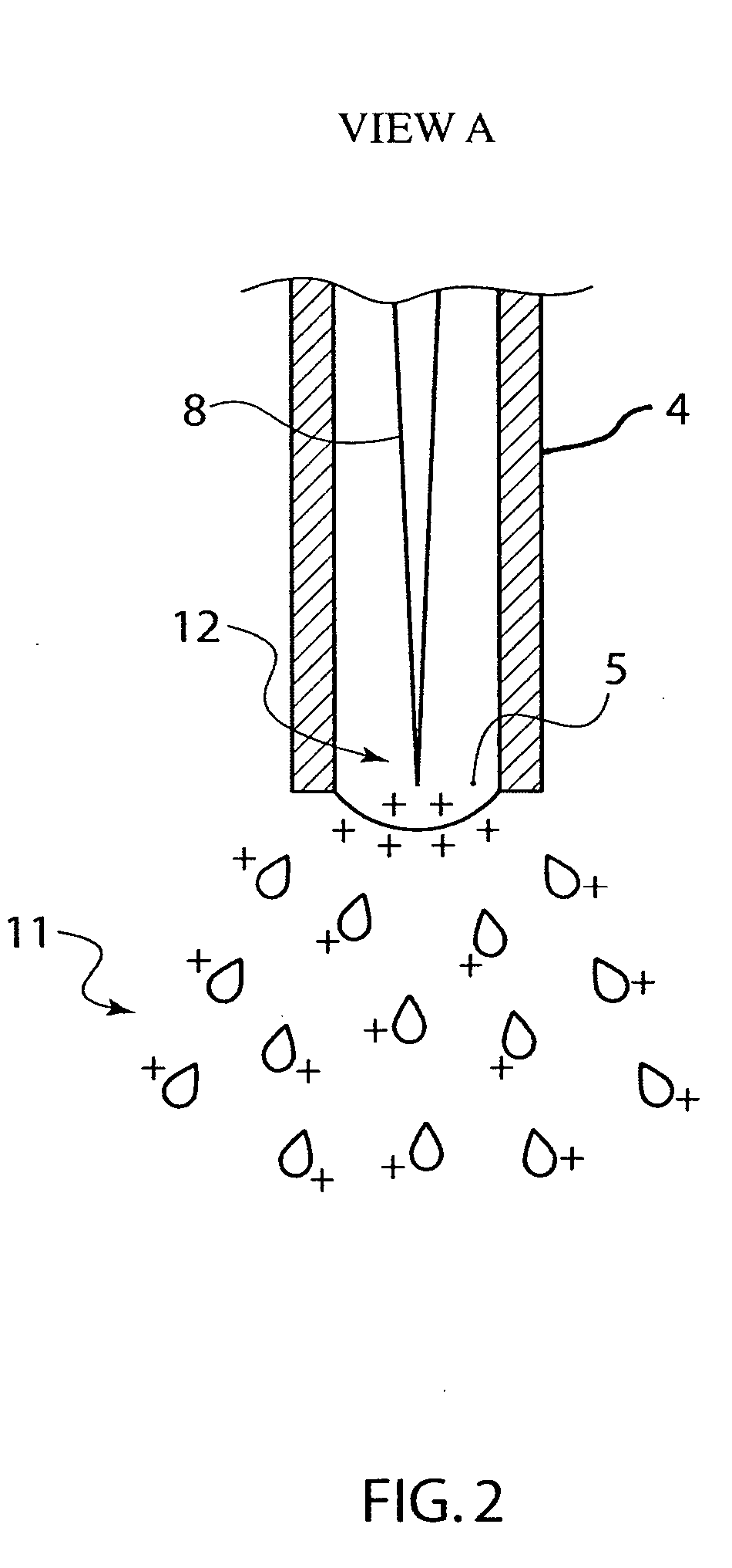
[0010] In certain embodiments of the invention, there is an apparatus in which the coating material spray dispenser device or nozzle body is made of electrically insulating material and includes an electrically conductive electrode having a proximal end positioned near an orifice in the coating material dispensing device. The medical device to be coated is held at a first electrical potential and a second electrical potential is applied to the electrode in the spray dispenser to inject charge into the adjacent coating material in communication with the electrode via either field emission of electrons or localized field ionization of the coating material, thereby causing the consequently formed coating droplets or coating particles to accelerate toward the medical device from the orifice in the dispensing device. This approach to electrospraying allows an electrically insulative coating material or coating solution below 0.01 μSiemens / cm (along with electrically conductive coating materials or solutions) to be used to coat medical devices, such as metallic stents, because the localized field emission or field ionization can provide sufficient charge carriers necessary for successful electrospraying. The field-injection electrostatic spraying method permits better control of coating uniformity and structure, and coating particle size, thereby permitting enhanced control of kinetic drug release rates.
[0011] Additionally or alternatively, in certain embodiments of the invention, the localized field-injection of charge carriers in a coating material may be enhanced by sharpening the proximal end of the electrode to focus and concentrate the electric field strength at the sharpened end.
[0012] The present invention eliminates the requirement that the coating possess adequate liquid electrical conductivity for electrospraying; thus permitting a wider range of potential coating materials or solutions for medical devices. Low conductivity coatings can be used to produce medical devices with structures and properties tailored for drug release, among other desired features. For example, medical devices coated with a layer of nanoparticles to provide enhanced controllability of surface morphologies, such as surface porosity, smoothness and thickness, can now be created with low electrically conductive coating materials and solutions. In addition, different structures including fibroid, encapsulated or multiple-layer structures varying in porosity through its thickness may be achieved by modifying the process controls during electrospraying.
[0013] The present invention provides better control of coating particle size and kinetic drug release rates, better coating uniformity, and improved deposition efficiency rates for both electrically insulating as well as electrically conductive coating materials and solutions, thus improving coating material transfer to a target in a more cost-efficient manner.

Problems solved by technology

However, gas-assist coating methods have shown intrinsic problems in adequately controlling coating uniformity and coating quality through the generated coating droplet size distribution and resulting drying time of the coating film, which can affect the kinetic drug release rate in coatings with embedded drug particles.
In addition, gas-assist methods delivered by high-velocity gas streams may have low deposition efficiencies (as low as 5%) with either partial or incomplete deposition or excessive overspraying.
The remaining 95% of the coating solution is lost in excessive overspraying and is therefore wasted.
Deposition efficiencies are important as the coating materials (the active drug and polymer) have become more expensive, and product processing throughput have become limited by the coating efficiency rate (i.e., the coating process is the bottleneck or critical choke point in throughput processing).
Conventional electrospraying methods can have relatively high deposition efficiency rates (as high as a 60% efficiency rate) and can adequately control coating uniformity and droplet sizing for electrically conductive coating materials or solutions; however, controlling coating droplet sizes and maintaining a stable or robust spray coating process within the well-known “cone-jet” mode can become more difficult with low electrically conducting coating solutions.
Conventional electrospraying methods thus may be incompatible with insulative solutions.

Method used


Image

  • Apparatus and method for field-injection electrostatic spray coating of medical devices
  • Apparatus and method for field-injection electrostatic spray coating of medical devices
  • Apparatus and method for field-injection electrostatic spray coating of medical devices

Examples


Embodiment Construction

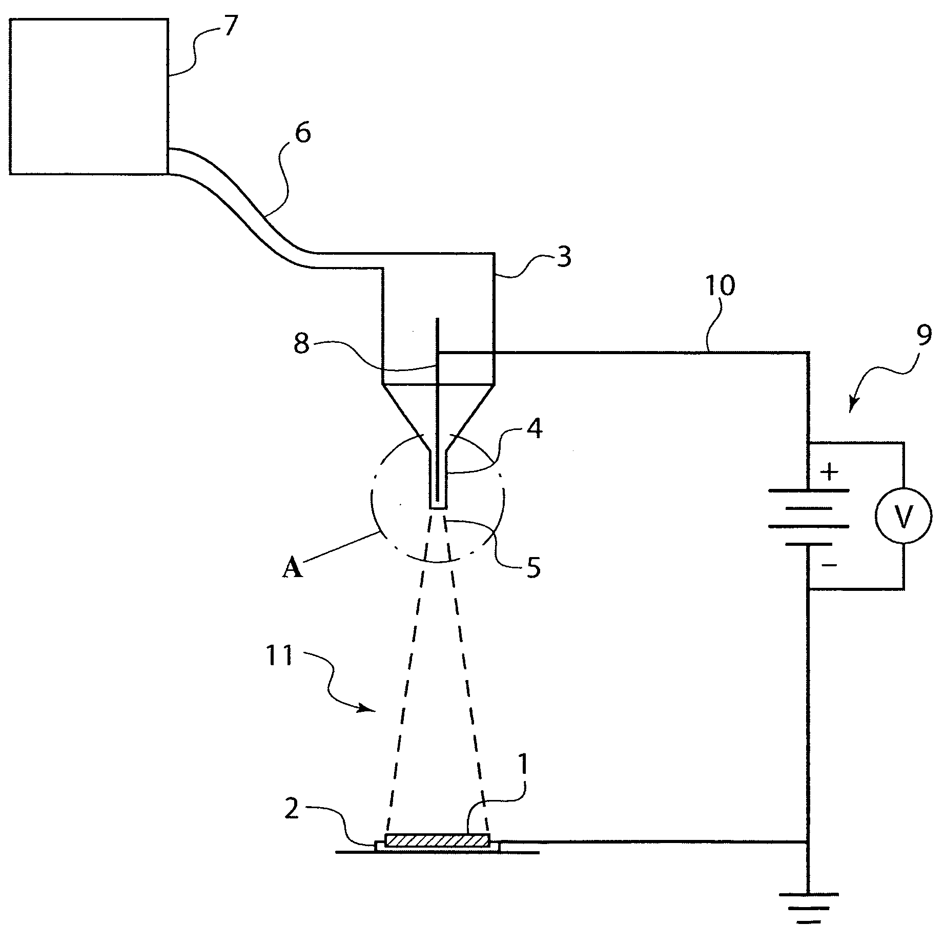
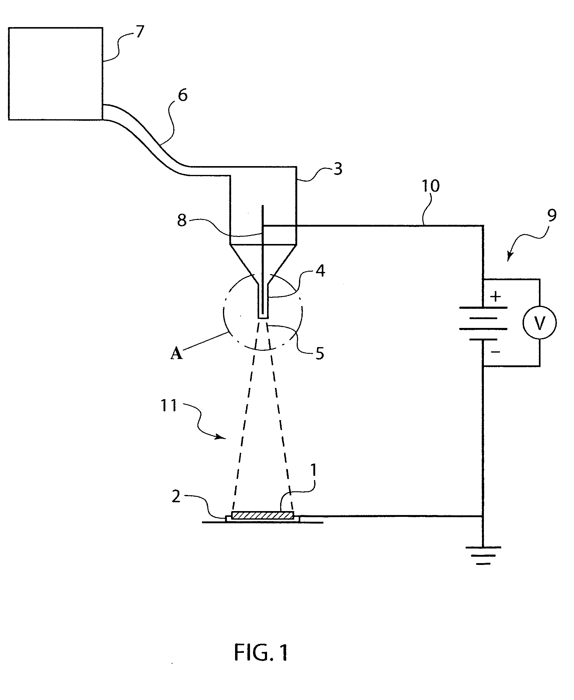
[0016] A first embodiment of the present invention is illustrated in FIG. 1. In this embodiment, a medical device 1 to be coated with a coating material is held and positioned by medical device holder 2. Medical device 1 in this instance is a stent that is to be coated with a therapeutic material. Although the medical device shown in FIG. 1 is illustrated as a stent, a variety of types of medical devices may be electrospray coated in the manner disclosed herein. In addition to holding stent 1 in a position suitable for coating application, medical device holder 2 can function as an electrode, and maintain the stent 1 and holder 2 at a first electrical potential. One of ordinary skill in the art would understand that medical device holder 2 may hold medical device 1 by any number of means, such as by the stent holders described in U.S. patent application Ser. No. 10 / 198,094, the disclosure of which is hereby expressly incorporated by reference herein. In the preferred embodiment, the...


PUM


Abstract

An apparatus and method for field-injection electrostatic spray deposition of medical devices like stents. The apparatus includes a medical device holder, which applies a first electrical potential to the medical device, and an electrically insulative electrostatic spray dispensing device having an electrically conductive electrode, which applies a second electrical potential, creating an electrical potential difference sufficient to attract charged coating material particles emitted from an orifice of the dispensing device toward the medical device. The electrode may be sharpened to create a localized, high-strength electric field to improve the charge injection into the coating material or coating solution.

Description

FIELD OF THE INVENTION [0001] The field of the present invention is application of coatings to medical devices, such as stents. More specifically, the present invention is directed to the field of electrostatic spraying of a fluid, such as a therapeutic fluid, to apply a coating to a medical device. BACKGROUND [0002] Medical implants are used for innumerable medical purposes, including the reinforcement of recently re-enlarged lumens, the replacement of ruptured vessels, and the treatment of disease such as vascular disease by local pharmacotherapy, i.e., delivering therapeutic drug doses to target tissues while minimizing systemic side effects. Such localized delivery of therapeutic agents has been proposed or achieved using medical implants which both support a lumen within a patient's body and place appropriate coatings containing absorbable therapeutic agents at the implant location. Non-limiting examples of such medical devices include catheters, guide wires, balloons, filters ...

Claims


Application Information

Patent Timeline
IPC IPC(8): B05D1/04H05C1/00B05B5/025
CPCB05B5/0255B05D1/06B05B5/0533
Inventor FENG, JAMESSHIPPY, JAMES LEE IIIFORSYTH, BRUCE
Owner BOSTON SCI SCIMED INC
Learn More