

Method for producing particles, particles, and sintered body
a technology of sintering body and particle, which is applied in the direction of prosthesis, phosphorus oxides, impression caps, etc., can solve the problems of amorphous particles obtained by this method, lack of stability of strength and porosity of sintered bodies obtained by sintering molded bodies, and high cost. , to achieve the effect of high strength and excellent dimensional accuracy
- Summary
- Abstract
- Description
- Claims
- Application Information
AI Technical Summary
Benefits of technology
Problems solved by technology
Method used
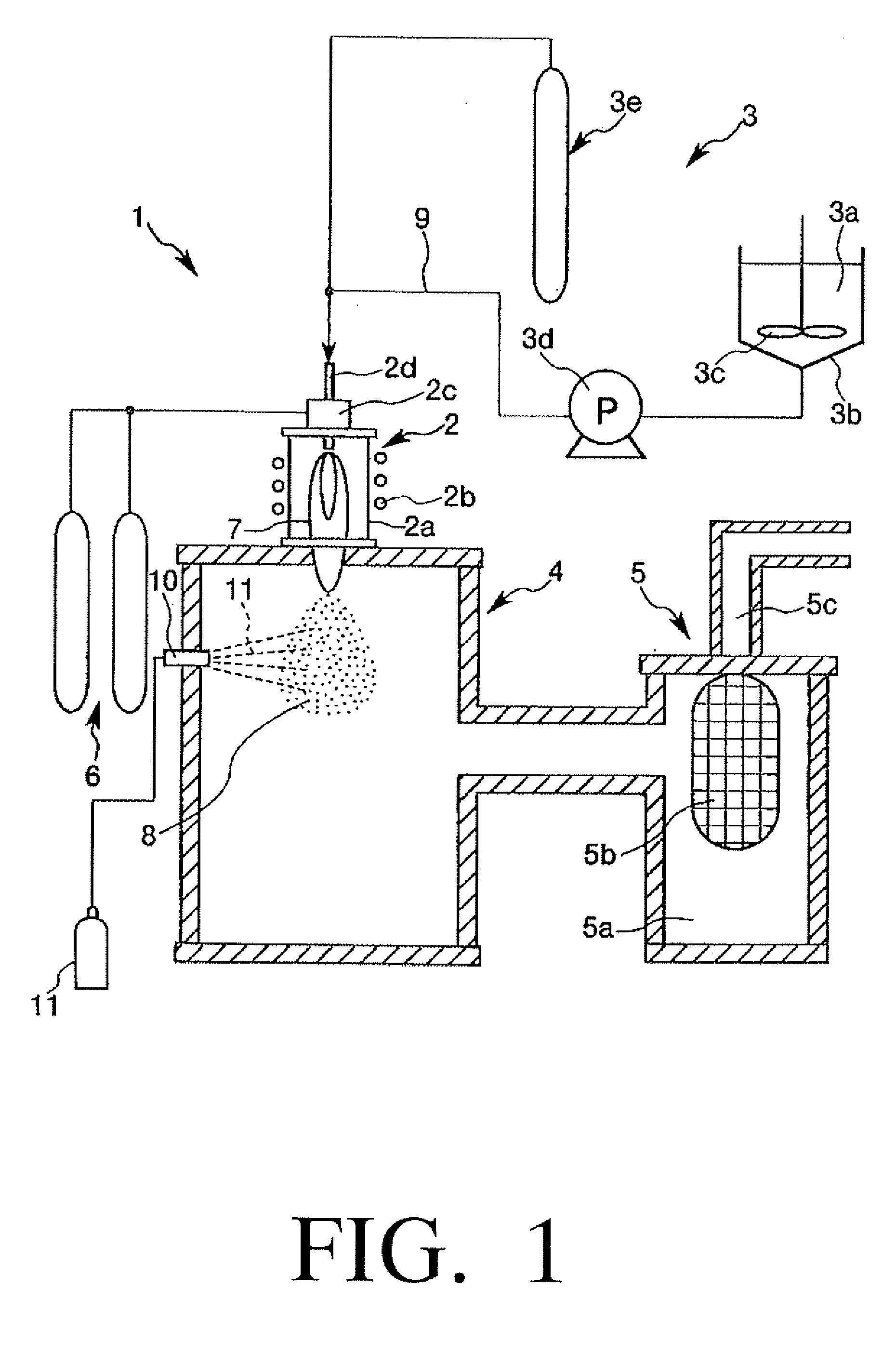
Image

Examples
example 1
[0138] First, 0.18 mol of diphosphorus pentoxide (first substance) and 0.6 mol of calcium nitrate tetrahydrate (second substance) were added to 900 mL of a 95 vol % aqueous ethanol solution (solvent) so that a Ca / P ratio was 1.67, and then the resultant mixture was stirred at room temperature (25° C.) for 4 hours to gelate the mixture. In this way, a slurry containing a reaction product was obtained.
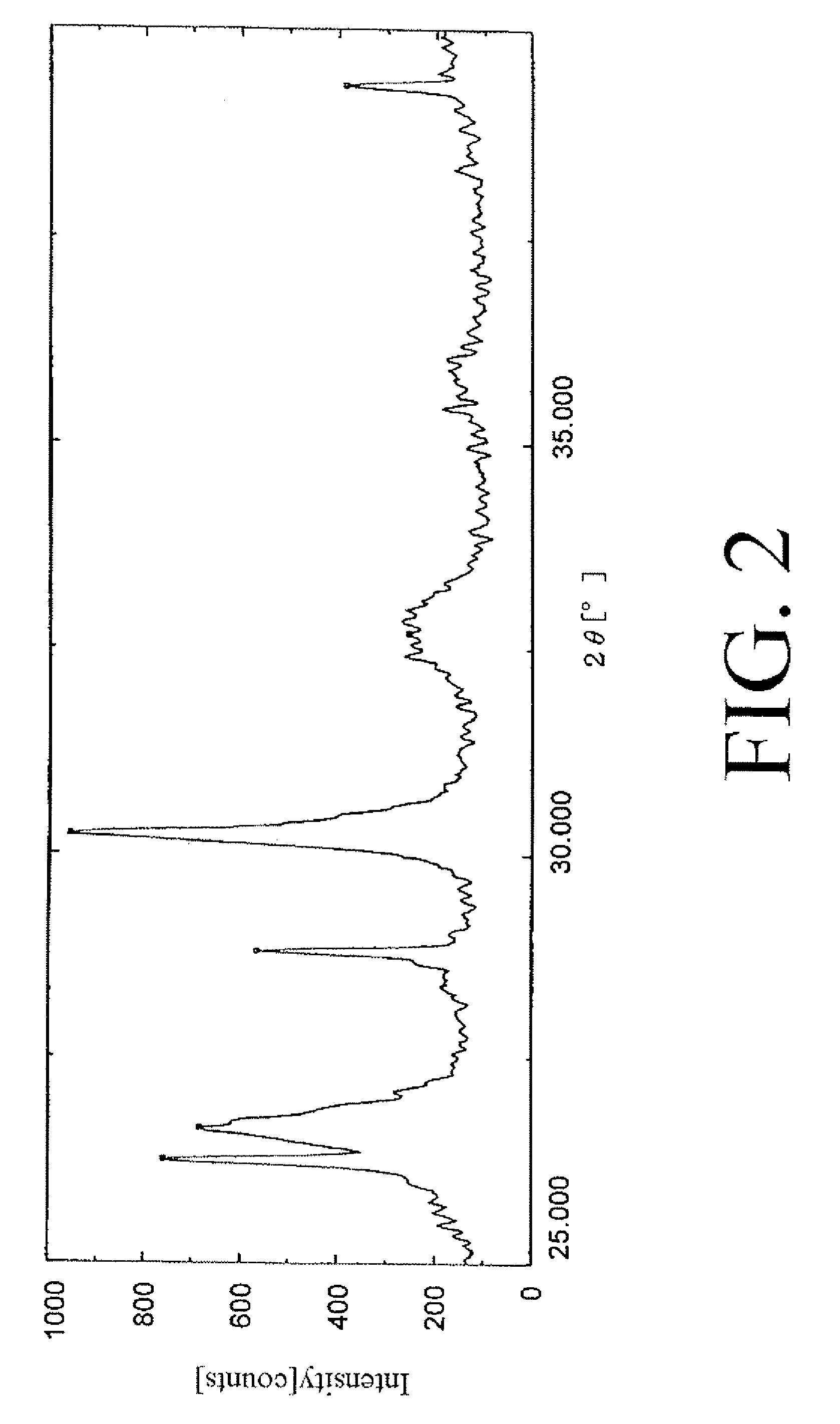
[0139] Then, the aqueous ethanol solution was removed from the slurry, and the remaining reaction product was subjected to X-ray diffraction (XRD) analysis to analyze the crystal structure thereof. The result of analysis (X-ray diffraction spectrum) is shown in FIG. 2.
[0140] As can be seen from FIG. 2, some peaks are observed in the X-ray diffraction spectrum of the reaction product but the spectrum is wholly broad. From the result, it can be considered that the reaction product is predominantly amorphous.
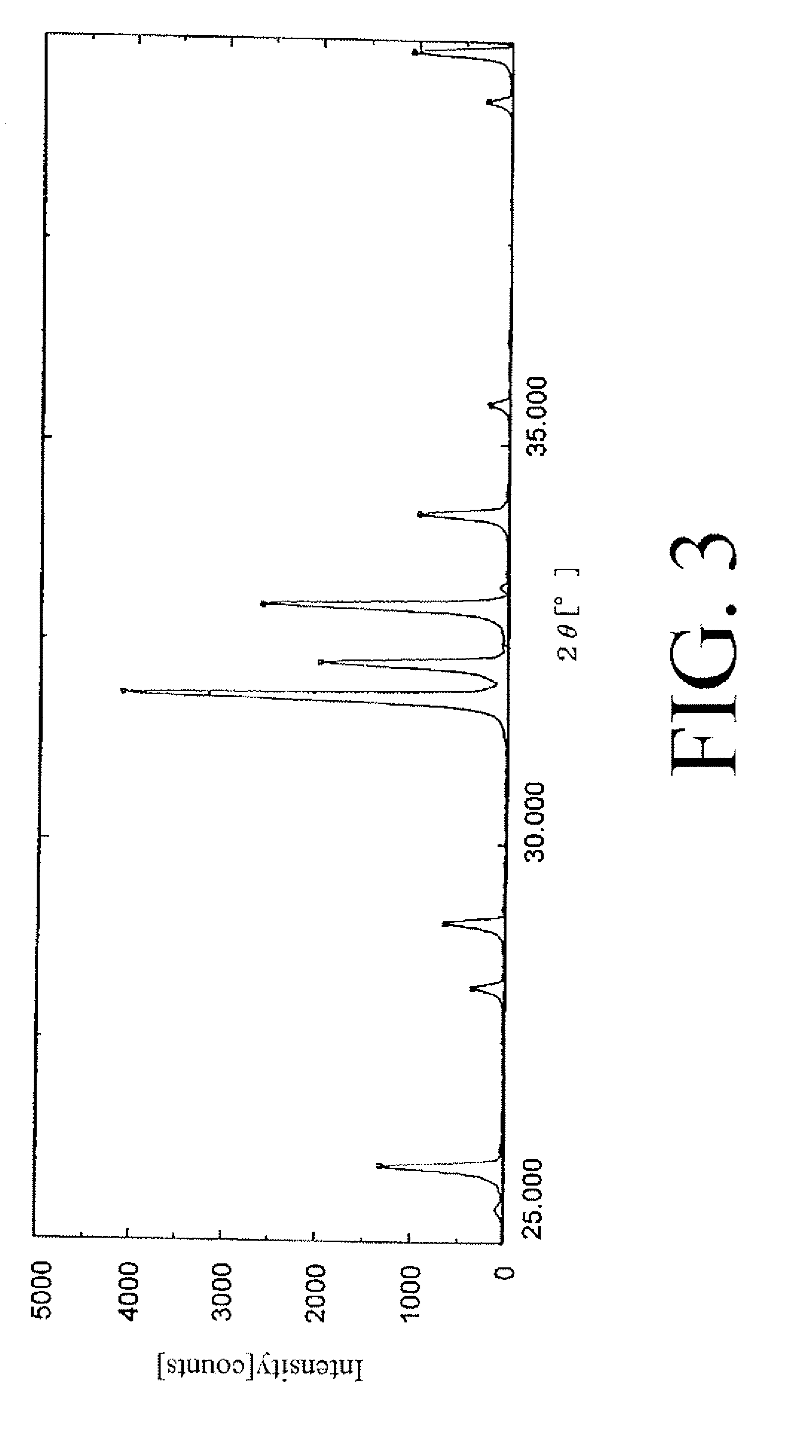
[0141] Next, the slurry obtained in was atomized into the plasma flame 7 produc...
example 2
[0146] Fine particles were produced in the same manner as in the Example 1 except that calcium ethoxide (0.6 mol) was used as the second substance instead of calcium nitrate tetrahydrate.
example 3
[0147] Fine particles were produced in the same manner as in the Example 1 except that a mixture of calcium nitrate tetrahydrate (0.3 mol) and calcium ethoxide (0.3 mol) was used as the second substance instead of calcium nitrate tetrahydrate.
PUM
| Property | Measurement | Unit |
|---|---|---|
| particle diameter | aaaaa | aaaaa |
| particle diameter | aaaaa | aaaaa |
| temperature | aaaaa | aaaaa |
Abstract
Description
Claims
Application Information