Reversal imprint technique

a technology of imprinting and imprinting, applied in the field of micro/nanoscale structures, can solve the problems of reducing the resolution and fidelity of the final pattern or structure, restricting the type of substrate that can be used, and limiting the type of nanostructure produced on many potential substrates, so as to achieve the effect of low residue thickness

Inactive Publication Date: 2007-03-15
AGENCY FOR SCI TECH & RES +1
View PDF10 Cites 41 Cited by
  • Summary
  • Abstract
  • Description
  • Claims
  • Application Information

AI Technical Summary

Benefits of technology

[0019] According to another alternative embodiment of this invention, the applied polymer coating is substantially planar and the temperature is substantially equal to, or below, the glass transition temperature (Tg) of the polymer. In this embodiment of the invention, imprinting occurs without any substantial lateral polymer movements and the entire coated polymer layer is transferred to the substrate. Under this embodiment of the invention, the resultant molded polymer coating is a negative replica of the mold. In this embodiment in which the whole polymer coating is transferred to the substrate, a further benefit is that low residue thickness is achieved.

Problems solved by technology

At present, there are strict limitations on the type of substrate that can be used; often only flat hard substrate surfaces can be imprinted.
Furthermore, unduly high temperatures and / or pressures are often required which can limit the type of nanostructure produced on many potential substrates.
These techniques not only require many process steps, but also involve deep etching to remove the thick planarization polymer layer created during formation, which often degrades the resolution and fidelity of the final pattern or structure formed.

Method used


Image

  • Reversal imprint technique
  • Reversal imprint technique
  • Reversal imprint technique

Examples


Embodiment Construction

[0037] Experimental

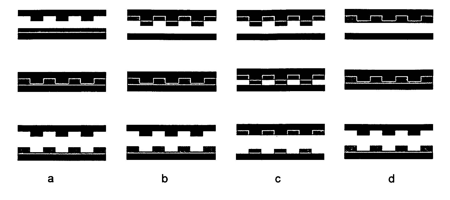
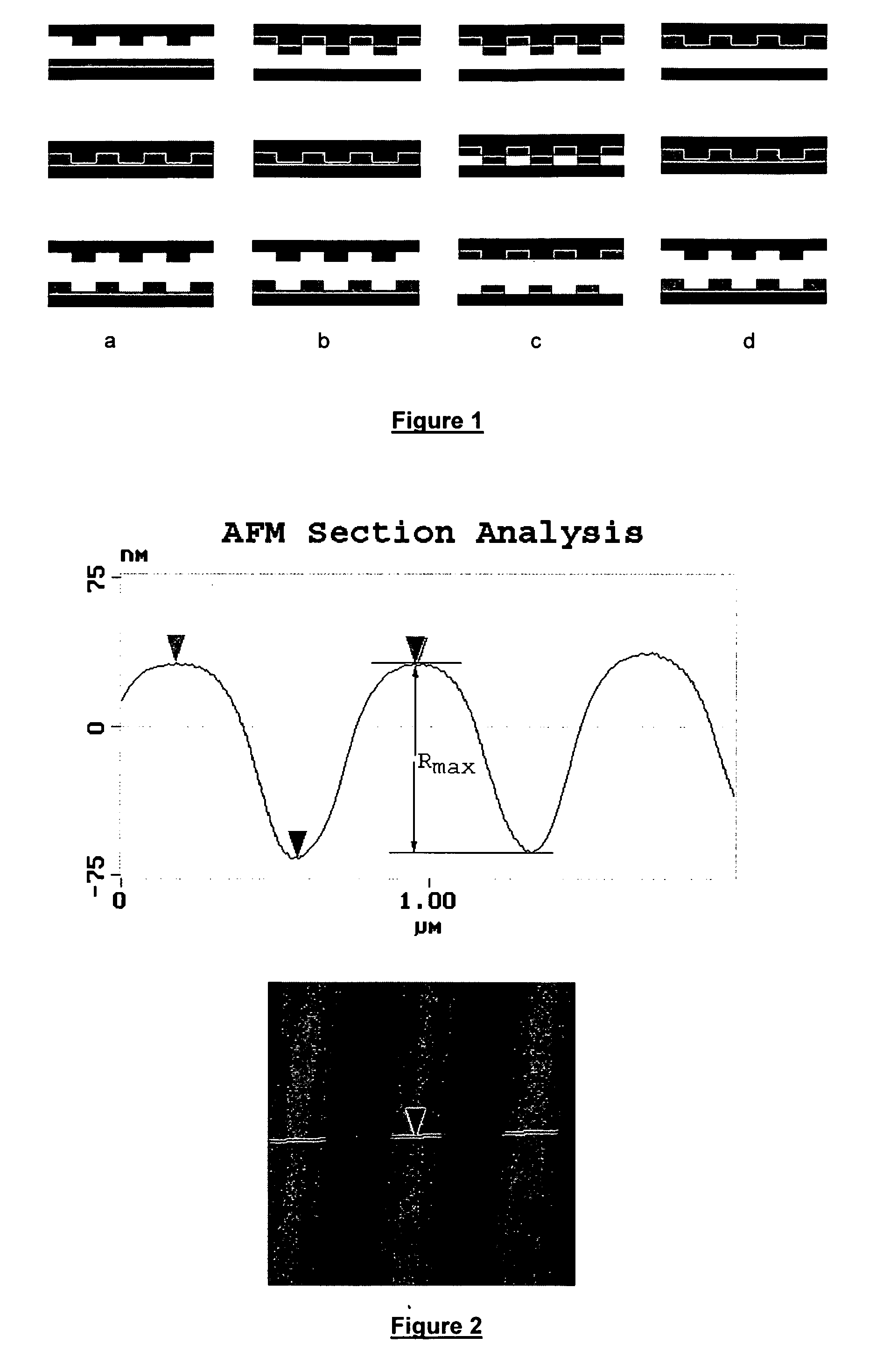
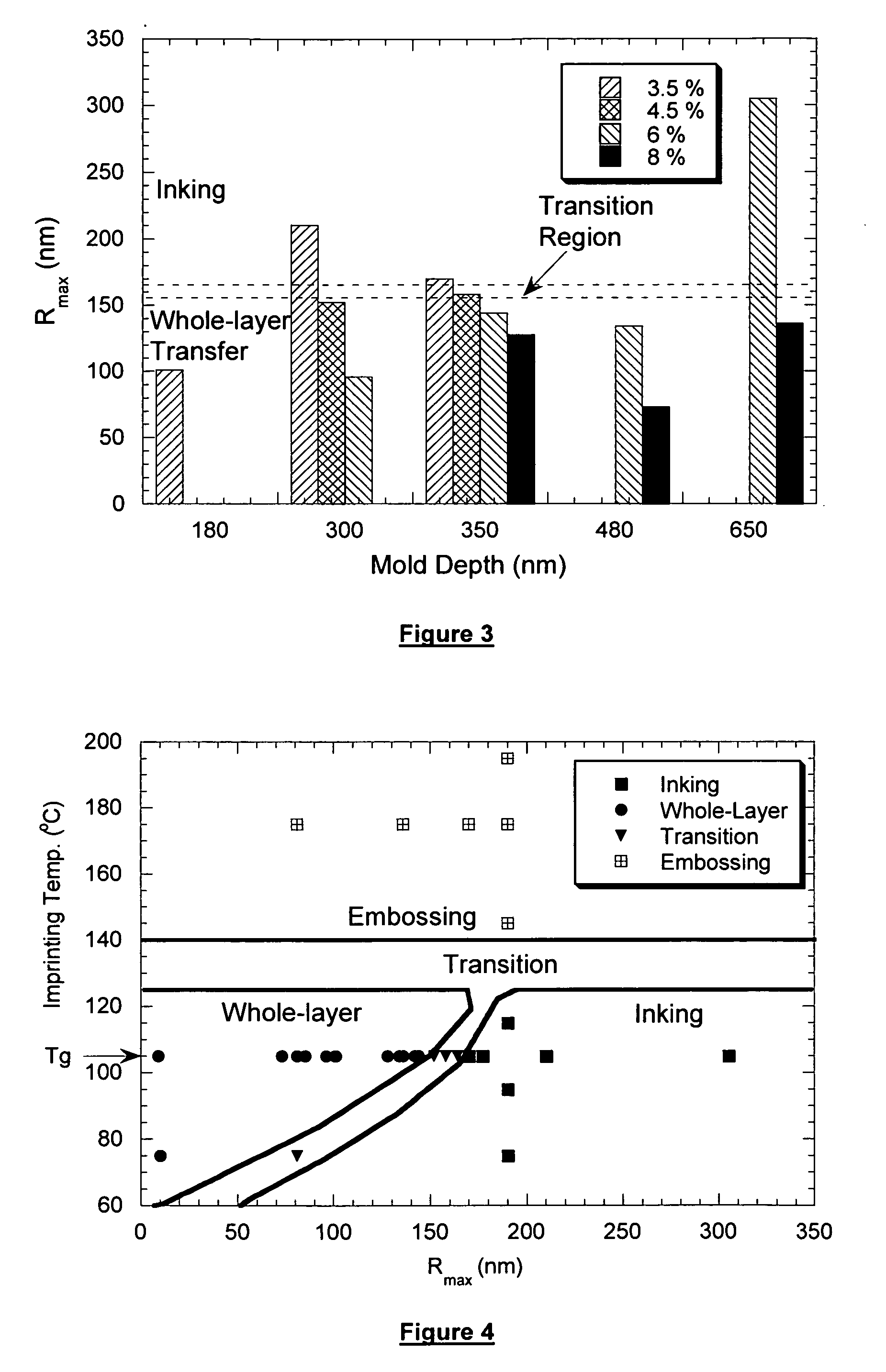
[0038] Two kinds of patterned molds were used in our study. The molds were made in SiO2 on silicon (Si) wafer and patterned by optical lithography and subsequent dry etching. One mold had features varying from 2 to 50 μm and a nominal depth of 190 nm. The other mold had uniform gratings with a 700 nm period and a depth ranging from 180 to 650 nm. All molds were treated with an surfactant, 1H,1H,2H,2H-perfluorodecyl-trichlorosilane, to promote polymer release. The substrates used were polished (100) Si wafers and flexible, 50 μm thick polyimide films (Kapton®). Poly(methyl methacrylate) (PMMA) with a molecular weight of 15,000 was used for imprinting. In a typical reversal imprinting experiment, a mold was spin coated with a PMMA toluene solution at a spin rate of 3,000 rpm for 30 seconds and then heated at 105° C. for 5 min to remove residual solvent. The coated mold was pressed against a substrate in a pre-heated hydraulic press under a pressure of 5 MPa for 5 m...


PUM

PropertyMeasurementUnit
pressureaaaaaaaaaa
pressureaaaaaaaaaa
Tgaaaaaaaaaa

Abstract

The present invention relates to a method for imprinting a micro-/nano-structure on a substrate, the method comprising (a) providing a mold containing a desired pattern or relief for a microstructure; (b) applying a polymer coating to the mold; and (c) transferring the polymer coating from the mold to a substrate under suitable temperature and pressure conditions to form an imprinted substrate having a desired micro-/nano-structure thereon.

Description

CROSS REFERENCE TO RELATED APPLICATION [0001] This application claims priority to International Application PCT / SG2002 / 000084 filed May 8, 2002.FIELD OF THE INVENTION [0002] The present invention relates to micro- / nano-scale structures and methods for forming such structures by reversal imprinting. [0003] Statement of the Art [0004] The demand to rapidly and economically fabricate nanoscale structures is a major driving force in the development of nanoscience and nanotechnology. Nanoimprint lithography (NIL), also known as hot embossing lithography, in which a thickness relief is created by deforming a polymer resist through embossing with a patterned hard mold, offers several decisive technical advantages, in particular as a low-cost method to define nanoscale patterns (S. Y. Chou, P. R. Krauss and P. J. Renstrom, Science, 272, 85 (1996) S. Y. Chou, U.S. Pat. No. 5,772,905). It has already been demonstrated that NIL is capable of patterning features with a lateral resolution down t...

Claims


Application Information

Patent Timeline
Patent Type & Authority Applications(United States)
IPC IPC(8): B05D5/12B41M5/00B05D3/12B29C33/42B81C1/00G03F7/00H01L21/027H05K3/00
CPCB29C33/42B82Y10/00Y10T428/24802G03F7/0002H05K3/0079B82Y40/00
Inventor HUANG, XUDONGBAO, LI-RONGCHENG, XINGGUO, LINGJIE J.PANG, STELLA W.
Owner AGENCY FOR SCI TECH & RES
Why Eureka
Try Eureka