Solid polymer electrolyte and process for making same

Active Publication Date: 2007-03-29
WL GORE & ASSOC INC
View PDF55 Cites 95 Cited by
  • Summary
  • Abstract
  • Description
  • Claims
  • Application Information

AI Technical Summary

Benefits of technology

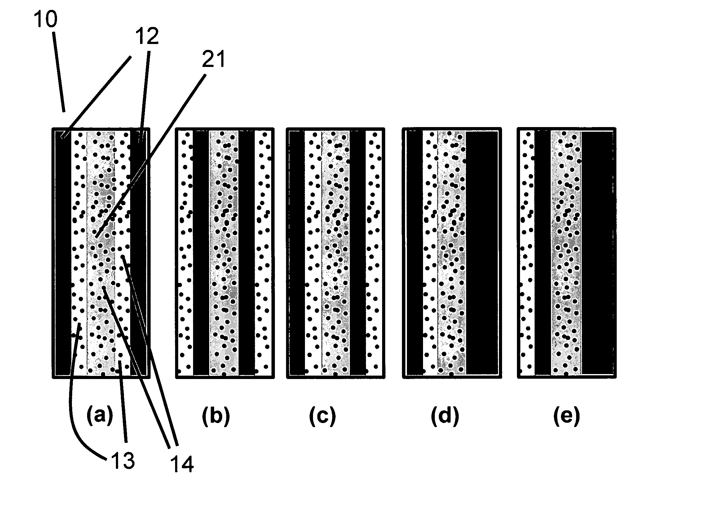
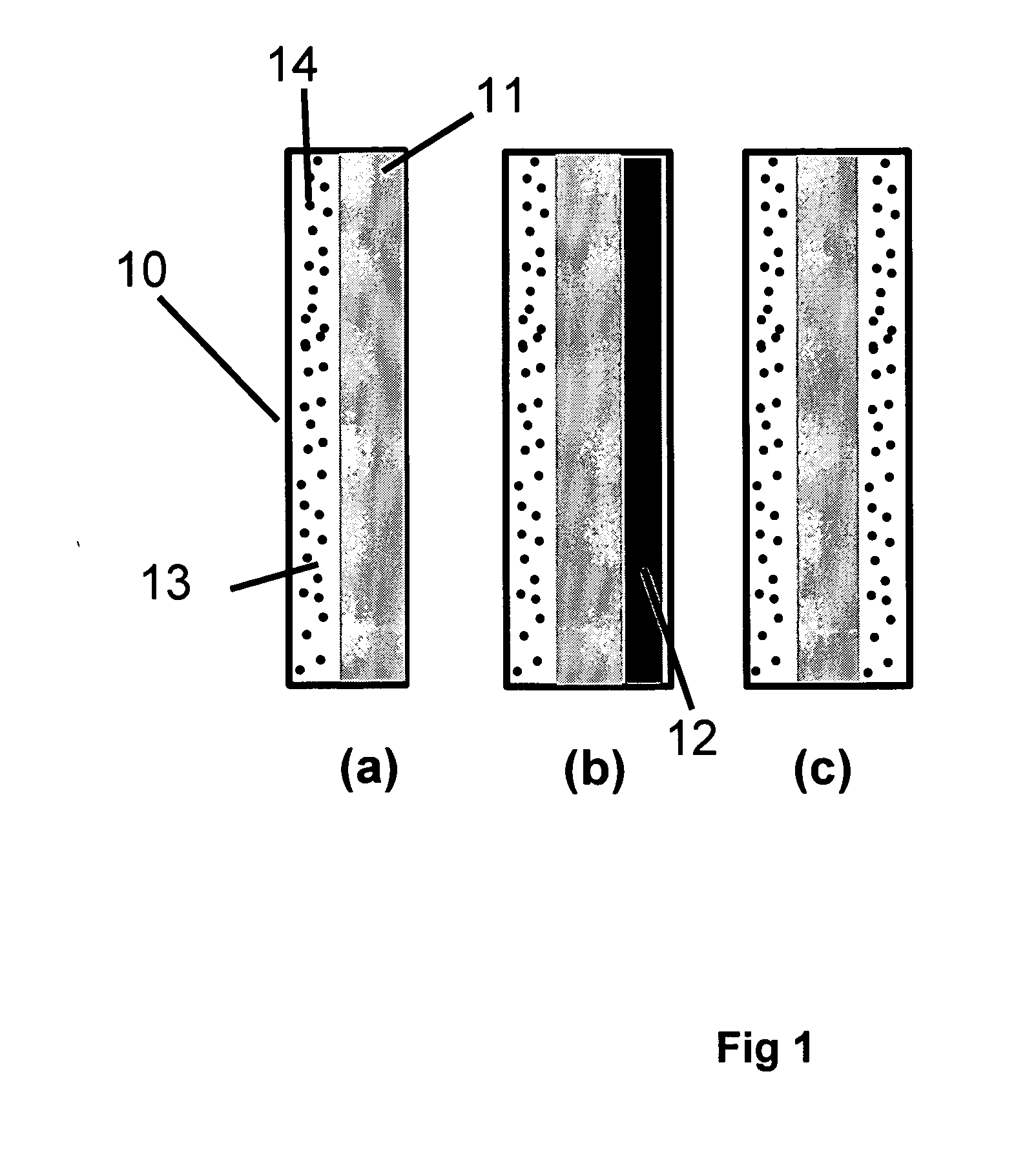
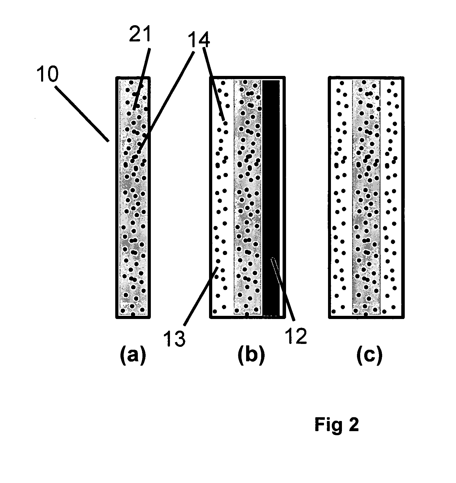
[0022] The instant invention of this application includes a solid polymer electrolyte membrane having a first surface and a second surface opposite the first surface, where the solid polymer electrolyte membrane has a failure force greater than about 115 grams and comprises a composite membrane consisting essentially of (a) at least one expanded PTFE membrane having a porous microstructure of polymeric fibrils, and (b) at least one ion exchange material impregnated throughout the porous microstructure of the expanded PTFE membrane so as to render an interior volume of the expanded PTFE membrane substantially occlusive; (c) at least one substantially occlusive, electronically insulating first composite layer interposed between the expanded PTFE membrane and the first surface, the first composite layer comprising a plurality of first carbon particles supporting a catalyst comprising platinum and an ion exchange

Problems solved by technology

As with any electrochemical device that operates using fluid reactants, unique challenges exist for achieving both high performance and long operating times. In order to achieve high performance it is necessary to reduce the electrical and ionic resistance of components within the device.
However, many technical challenges are still ahead.
Should the membrane degrade during fuel cell operation, it tends to become thinner and weaker, thus making it more likely to develop holes or tears.
Should this occur, the oxidizing gas and fuel may mix internally potentially leading to internal reactions.
Because such an internal reactions may ultimately cause damage to the entire system, the fuel cell must be shut down.
However, reducing the membranes physical thickness can increase the susceptibility to damage from other device components leading to shorter cell lifetimes. Various improvements have been developed to mitigate this problem.
Although the process described in '132 does describe a process to form an electrocatalytic fi

Method used


Image

  • Solid polymer electrolyte and process for making same
  • Solid polymer electrolyte and process for making same
  • Solid polymer electrolyte and process for making same

Examples


example 1

[0117] In Example 1, a solid polymer electrolyte membrane was prepared as follows:

[0118] A concentrated catalyst ink consisting of platinum on a carbon support (type V11-D50 catalyst, Englehard Corporation, Iselin, N.J.) at a 1:1 weight ratio (35% water by weight), Type 1 ion exchange material, and normal propanol in the following approximate ratios, respectively, 8.54%, 4.27%, and 87.19% was prepared. This was accomplished as follows. A slurry was prepared by mixing a portion of the n-propanol with the catalyst powder in an 30 liter glass reactor (H. S. Martin, Inc., Vineland, N.J.) after evacuating it, and refilling with nitrogen. Subsequently, the slurry was pumped into a 50 liter vessel where agitation was supplied for 20 minutes by a rotor / stator agitator (Model AX200 by Silverson Machines Inc., Longmeadow, Mass.) while the solution was recirculated through a ISG motionless static mixer (Charles Ross & Sons, Hauppauge, N.Y.). To this slurry, the ionomer was added continuously ...

example 2

[0122] To illustrate the importance of the mechanical properties of the solid polymer electrolytes to the inventive materials herein, a material was made that is otherwise identical to an embodiment of the inventive materials, but has weaker mechanical properties. It thus has low fluoride release rates indicative of a chemically stable membrane, but its life is not as long as Example 1 because the polymer electrolyte membrane is not as strong as that formed in Example 1. The solid polymer electrolyte of this example was prepared as follows. First, an ePTFE membrane was prepared according to the teachings of Gore in '566 with an average mass per area of about 3.3 g / m2, a thickness of about 7.8 microns, an average ball burst strength of about 1.18 lbs, and an average Frazier number of about 42 ft3 / min / ft2 at 0.5 inches of water. The ball burst is a standard test (see for example, U.S. Pat. No. 5,814,405 to Branca, et. al.) performed on porous membranes that measures the relative stren...

example 3

[0126] To confirm the importance of the mechanical properties together with the composite layer comprising a catalyst on a supporting particle, another solid polymer electrolyte was prepared that had a composite layer of catalyst on supporting particle but had low mechanical properties. This was done as follows. A Type 1 ion exchange material with 0.8% Pt to dry ionomer weight was prepared using the procedures of Example 1. The drawdown bar was set to 0.025 cm (0.010 inches) and only one coating was done directly onto a glass substrate (no polymer film). No ePTFE was used. After drying, the solid polymer electrolyte was removed in room temperature water. The resulting solid polymer electrolyte was 20 to 26 microns thick.

[0127] The mechanical properties measured on a separate piece of this same material show that it is significantly weaker than those measured on the material of Ex. 1 (Table 6)

[0128] A different section of this solid polymer electrolyte was prepared into an MEA usin...


PUM

PropertyMeasurementUnit
Fractionaaaaaaaaaa
Fractionaaaaaaaaaa
Fractionaaaaaaaaaa

Abstract

A solid polymer electrolyte membrane having a first surface and a second surface opposite the first surface, where the solid polymer electrolyte membrane has a failure force greater than about 115 grams and comprises a composite membrane consisting essentially of (a) at least one expanded PTFE membrane having a porous microstructure of polymeric fibrils, and (b) at least one ion exchange material impregnated throughout the porous microstructure of the expanded PTFE membrane so as to render an interior volume of the expanded PTFE membrane substantially occlusive; (c) at least one substantially occlusive, electronically insulating first composite layer interposed between the expanded PTFE membrane and the first surface, the first composite layer comprising a plurality of first carbon particles supporting a catalyst comprising platinum and an ion exchange material, wherein a plurality of the first carbon particles has a particle size less than about 75 nm, or less than about 50 nm, or less than about 25 nm.

Description

FIELD OF THE INVENTION [0001] The present invention relates to a solid polymer electrolyte and process for making it, as well as its use in a catalyst coated membrane and in polymer electrolyte membrane fuel cells. BACKGROUND OF THE INVENTION [0002] Fuel cells are devices that convert fluid streams containing a fuel, for example hydrogen, and an oxidizing species, for example, oxygen or air, to electricity, heat and reaction products. Such devices comprise an anode, where the fuel is provided; a cathode, where the oxidizing species is provided; and an electrolyte separating the two. The anode-electrolyte-cathode body is called the catalyst coated membrane herein. The fuel and / or oxidant typically is a liquid or gaseous material. The electrolyte is an electronic insulator that separates the fuel and oxidant. It provides an ionic pathway for the ions to move between the anode, where the ions are produced by reaction of the fuel, to the cathode, where they are used to produce the produ...

Claims


Application Information

Patent Timeline
IPC IPC(8): H01M8/10H01M4/96H01M4/92C08J5/22H01M4/88
CPCH01M4/8807H01M4/88H01M4/8828H01M4/92H01M4/926H01M8/1004H01M8/1023H01M8/1025H01M8/1027H01M8/103H01M8/1039H01M8/106H01M8/1062H01M8/1081Y02E60/521H01M4/881Y02E60/50H01M8/10H01M4/90Y02P70/50
Inventor BERTA, THOMASSHAMROCK, WILLIAMLIU, WEN
Owner WL GORE & ASSOC INC
Why Eureka
Try Eureka