Etch system with integrated inductive coupling

a high-density inductive coupling and etching technology, applied in the direction of coatings, electric discharge lamps, electric lighting sources, etc., can solve the problems of chamber contamination, sputtering of these surfaces, and inability to allow real current to flow from the electrode to the rf generator, etc., to achieve high efficiency and reduce costs.

Inactive Publication Date: 2007-05-24
TOKYO ELECTRON LTD
View PDF19 Cites 35 Cited by
  • Summary
  • Abstract
  • Description
  • Claims
  • Application Information

AI Technical Summary

Benefits of technology

[0014] An objective of the present invention is to provide a plasma source for utilization in a plasma process, such as plasma etching, plasma deposition or plasma cleaning, that is uniform across the surface of the substrate being processed. Another objective of the i

Problems solved by technology

Capacitively-coupled plasma sources include “planar diode” or “parallel plate” systems, in which a surface to be etched is placed on one electrode that is coupled to an RF generator through a blocking capacitor, which does not allow real current to flow from the electrode to the RF generator.
Capacitively-coupled sources have widespread use in semiconductor plasma processing, but have some problems and limitations.
In symmetrical systems, both electrodes can be subjected to high-energy ion bombardment, including energetic ion bombardment of walls and fixtures causing sputtering of these surfaces and chamber contamination.
Non-uniform plasma caused by large losses of electrons and ions to the chamber walls causes nonuniform etch rates to result.
Optimal geometry at low pressure has been cylindrical geometry, including that in hexode systems, which is not adaptable to 300 mm single wafer semiconductor manufacturing.
A common drawback of the above-described systems is an inability to independently

Method used


Image

  • Etch system with integrated inductive coupling
  • Etch system with integrated inductive coupling
  • Etch system with integrated inductive coupling

Examples


Embodiment Construction

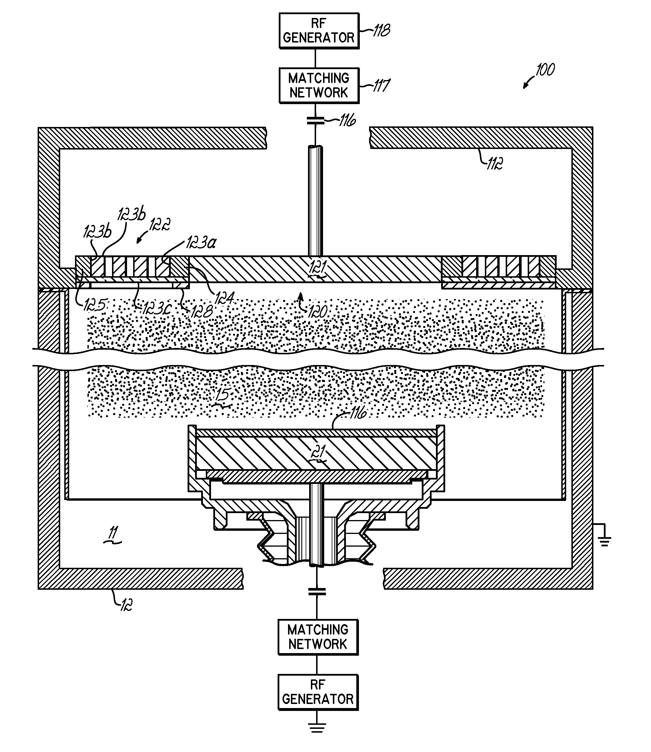
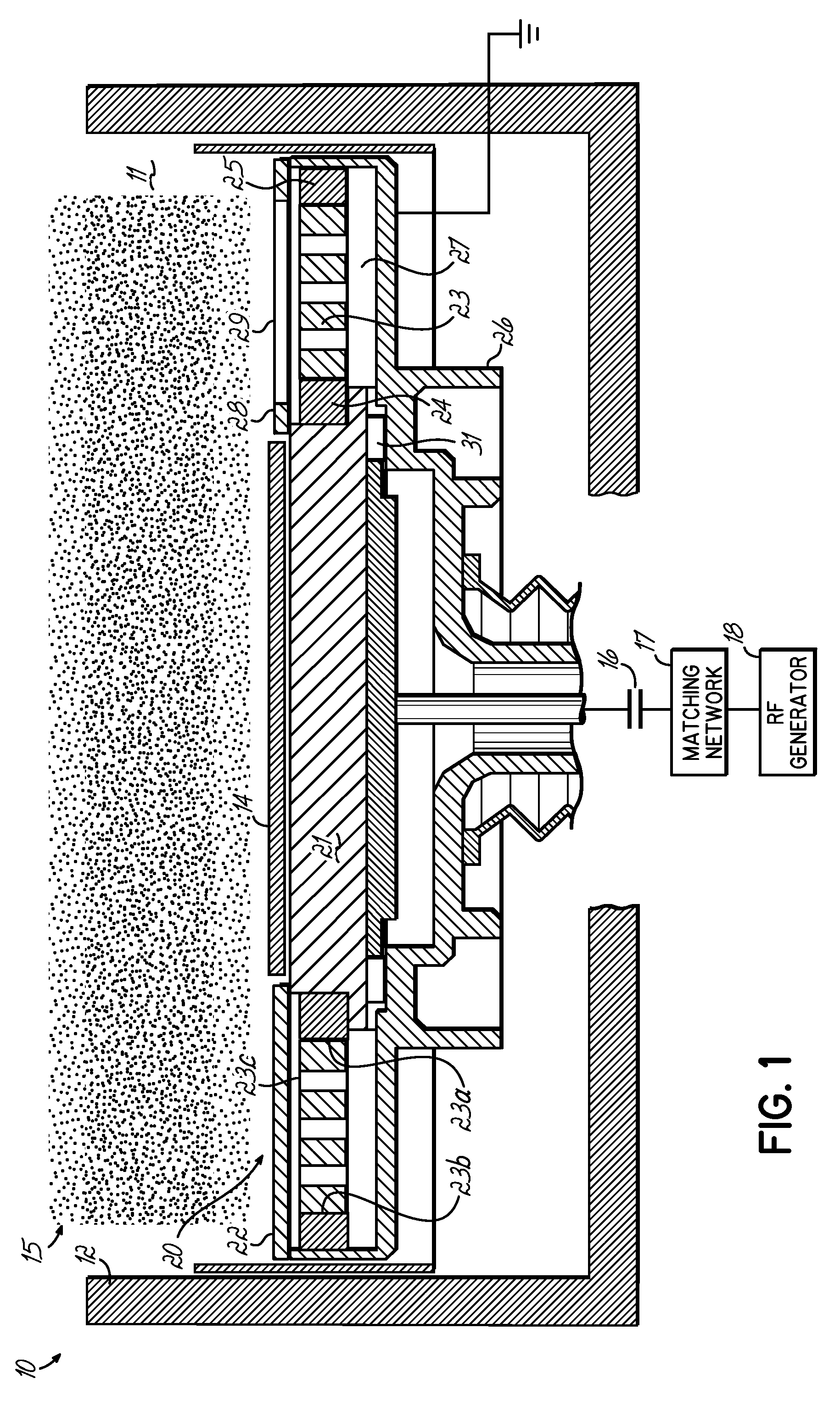
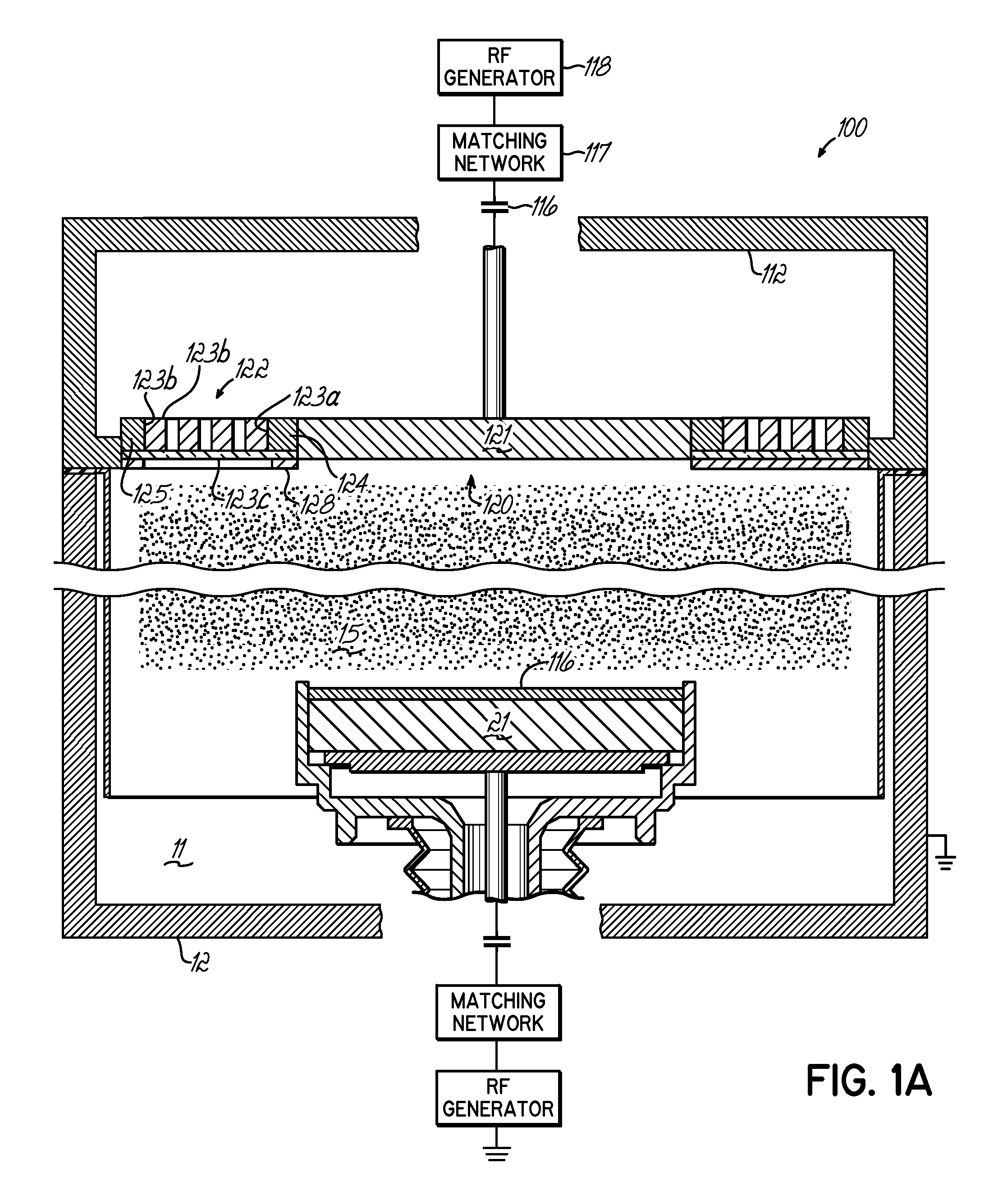
[0039] As illustrated in FIG. 1, according to one embodiment of the invention, a plasma processing apparatus 10 includes a vacuum processing chamber 11 enclosed in a chamber wall 12. An integrated, electrostatic inductively-coupled device or wafer support (i-ESIC) 20 is mounted in the chamber 11 to support individual wafers 14 thereon for processing by a plasma 15 maintained within the vacuum chamber 11.

[0040] Referring to FIGS. 1 and 2, the wafer support 20 has two integrated main components or portions: a capacitive-coupling component 21, which provides a capacitively-coupled RF path to a plasma 15, and an inductively-coupled component 22, which provides an inductively-coupled RF path to the plasma 15. The capacitively-coupled component 21 is a central substrate support portion, typically an electrostatic chuck (ESC), which holds individual wafers to the support 20 during processing. The chuck of the central portion 21 also provides control of the energy of ions from the plasma b...


PUM

PropertyMeasurementUnit
Magnetic fieldaaaaaaaaaa
Densityaaaaaaaaaa
Frequencyaaaaaaaaaa

Abstract

An integrated capacitively-coupled and inductively-coupled device is provided for plasma etching that may be used as a primary or secondary source for generating a plasma to etch substrates. The device is practical for processing advanced semiconductor devices and integrated circuits that require uniform and dense plasma. The invention may be embodied in an apparatus that contains a substrate support, typically including an electrostatic chuck, that controls ion energy by capacitively coupling RF power to the plasma and generating voltage bias on the wafer relative to the plasma potential. An etching electrode is provided opposite the substrate support. An integrated inductive coupling element is provided at the perimeter of the etching electrode that increases plasma density at the perimeter of the wafer, compensating for the radial loss of charged particles toward chamber walls, to produce uniform plasma density above the processed wafer. The device has a capacitive coupling zone in its center for energizing etching ions and an inductive coupling zone at its perimeter of the wafer. Both zones together with plasma create a resonant circuit with the plasma.

Description

[0001] This application is a Continuation-in-Part of U.S. patent application Ser. No. 10 / 716,729, filed Nov. 19, 2003, hereby expressly incorporated herein by reference herein.FIELD OF THE INVENTION [0002] This invention relates to high density plasma generating devices, systems and processes, particularly for the manufacture of semiconductor wafers and integrated circuits. This invention particularly relates to the high density inductively coupled plasma (ICP) and capacitively coupled plasma (CCP) sources used in semiconductor and integrated circuit processing. BACKGROUND OF THE INVENTION [0003] There are two principal groups of the plasma sources: capacitively-coupled plasma sources, which utilize RF electric field coupling to the plasma, and inductively coupled plasma (ICP) sources, which utilize RF magnetic field coupling to the plasma. [0004] Capacitively-coupled plasma sources include “planar diode” or “parallel plate” systems, in which a surface to be etched is placed on one ...

Claims


Application Information

Patent Timeline
IPC IPC(8): C23F1/00C23C16/00H01J37/32H01L21/306
CPCH01J37/321H01J37/32174H01J37/32C23C16/00
Inventor BRCKA, JOZEF
Owner TOKYO ELECTRON LTD
Why Eureka
Try Eureka