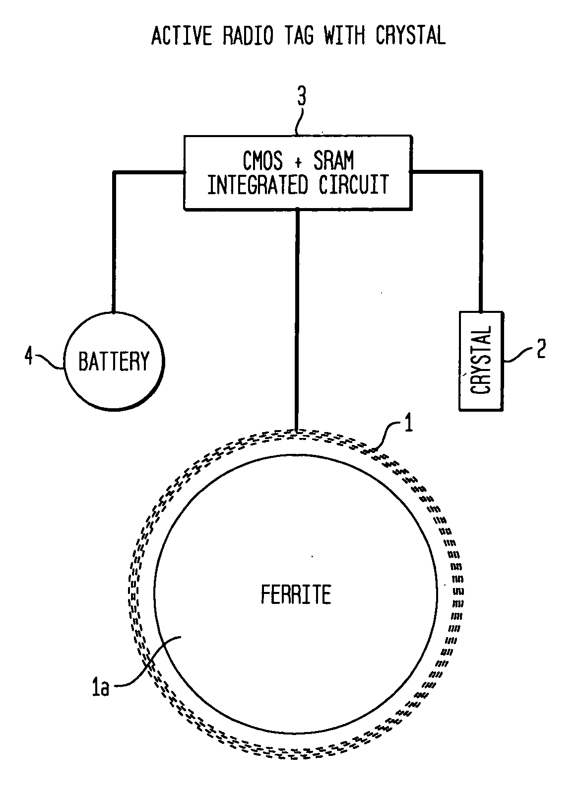
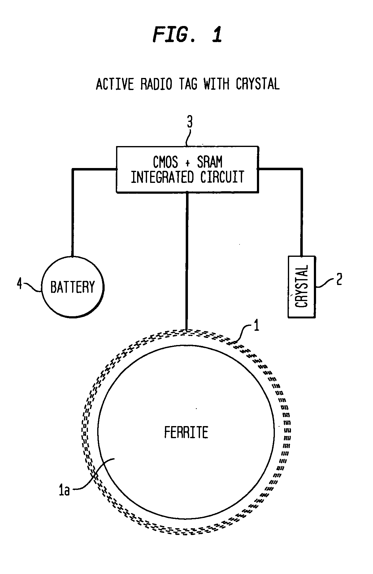
An active
transponder tag only eliminates the
crystal and requires the extra cost of battery.
As the transmission frequency goes down below 500 Khz, it is no longer possible to use optimal
Electric Field antennas on the tag or from the
base station, since the wave length is so very long (which requires a large antenna for
signal detection).
Often the algorithms used to network such HF / UHF tags may require complex circuitry in the
base station as well.
Finally, as the frequency goes up the cost of the integrated circuits require to read and write to the passive RF tags in the base
station also rises.
However, because of many other disadvantages described below, ULF tags are generally not used for other applications.
The major
disadvantage of ULF tags is that the detectable
radiant energy leaving the transmission antenna is largely a magnetic (M) field rather than an electric (E) field.
This magnetic mode of transmission (also called inductive transmission), has the major
disadvantage of short range.
Thus, the inductive or M
radiance mode of transmission will, theoretically and in practice, severely limit the distance of transmission to only a few inches.
In addition ULF tags are very slow because the carrier frequency (e.g. 100 Kz to 200 Khz) is low compared to HF and UHF.
Thus, in general it is often assumed that ULF radio tags will be more expensive since they do require a wound
wire antenna.
However, it is possible to make a low cost ULF passive tag with an antenna coil and
chip and no PC board (WO03094106A1) there are many other disadvantages with current commercial ULF tags.
Many of the commercial organizations recommending the higher HF?UHF frequencies believe that passive and or active radio tags in these low frequencies are not suitable for any of these applications for reasons given above.
The transmission speed is inherently slow using ULF as compared to HF and UHF since the tag must communicate with low
baud rates because of the
low transmission carrier frequency.
Many sources of
noise exist at these ULF frequencies from electronic devices, motors, florescent ballasts, computer systems, and power cables.
Thus ULF is often thought to be inherently more susceptible to
noise.
Radio tags in this ULF frequency range are thought to be more expensive since they require a wound coil antenna because of the requirement for many turns to achieve optimal electrical properties (maximum Q).
Current networking methods used by
high frequency tags, as used in HF and UHF, are impractical due to such low bandwidth of ULF tags described above in point 2 immediately above.
Many, unexpected functional disadvantages have recently been discovered with actual widespread use of passive radio HF, and UHF tags in the field (“Radio tags are falling off the fast track”, The Boston Globe, Scott Kirsner, May 31, 2004; “Despite Wal-Mart's Edict, Radio Tags Will Take Time”, The New York Times, Barnaby Feder, Dec. 28, 2004).
Passive HF and UHF
transponder tags transmit with limited power since they can obtain power only from a rectified
carrier signal.
In some tags this power requirement may limit the transmission range to only a few inches or at most to a few feet.
If tag is twisted by 20-30 degrees from parallel to the plane of the antenna the
signal may drop enough to lead to a read failure.
This is due to the limited
dynamic range of the
amplifier used in these tags since it is powered by the antenna coil.
This is part due to limited transmission power, but also in part due to fact higher frequency radio signals reflect or are blocked by any conductive surface or material, and high frequencies are absorbed and as a result effectively blocked by liquids.
The direct cost associated with this
external database is often difficult to predict in advance of any use and often requires additional expensive hardware such as a
wireless handheld computer to identify an item in the field.
“Writing to a tag before it is affixed to a container increases the risk of
product mix-ups.
This memory requirement in passive tags has several unexpected disadvantages: The cost of an
EEPROM significantly raises the cost of the passive transponder tags since it involves many extra
processing steps in the production of the
integrated circuit.
Again, costs of an integrated circuit is directly related to its area.
As a result most applications using passive HF / ULF tags use a large fixed ID that must be programmed as described under point 5, above, and this leads to significant increased IT (
information technology) costs.
EEPROM storage requires significantly more power than conventional SRAM and this additional power requirement may also reduce read distance and increase angle sensitivity, especially if many reads and writes to memory are required.
In practice, because of the increased size of the
chip, speed, and related power requirements, passive RF chips are limited to about 2,048 bits or 256 bytes of memory.
In many applications where data may have to be logged repeatedly over long period of time (temperature for example) this storage size is not sufficient.
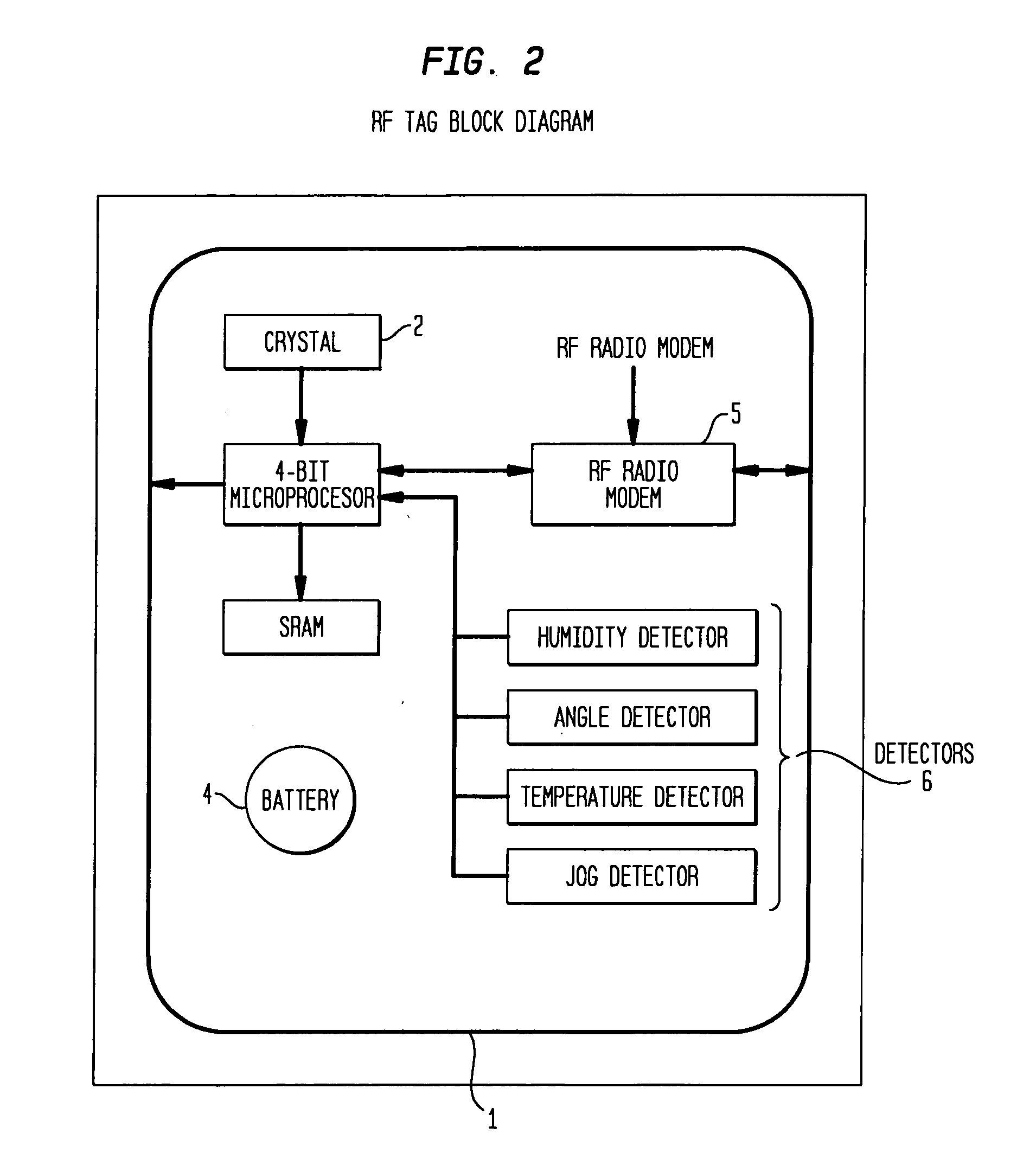
In many cases, especially in healthcare applications, it may also be important to frequently monitor the temperature or
humidity of the product, and this cannot be carried out without some source of power.
Also, an RF tag cannot
record temperature along with time—either as a
histogram or data log, without an active clock and
time of day that is independent of the carrier frequency.
However, this additional power requirement of an LED would lead to both significant reduction in range of
signal transmission by the tag and an increased angle sensitivity of the tag.
It is difficult to place a reader on a wall and guarantee that it is possible to capture data as the
wrist-tagged patient passes by.
The handheld reader that is needed to read a HF / UHF tag may be quite expensive for several reasons.
Firstly, the read / write circuitry of the reader must be complex in order to make the radio tag correspondingly low cost and simple.
This may require that the handheld reader be equipped with a longer range RF link to a computer, thereby further adding to the cost.
However, since the tag has no memory or limited memory, and no clock to keep track of date and time, it is difficult to provide any public key or
encryption protocols that could provide reasonable security systems as a proof of identity or proof of the tag's
data content.
Thus, many unexpected complex issues have appeared as passive HF / UHF RFID tags have been put into widespread use for detection and tracking of animate and inanimate objects attached to the tags.
While many of the current passive transponder tags can be used in applications that do not require significant memory and do require high speed, many of the existing commercial passive transponder tags can not be used reliably in applications that might make use of steel or
metal shelves, on liquid products, or in applications that must read near or in living animals or humans (eg.
livestock identification) especially on injectable or liquid pharmaceuticals, or on medical devices such as DES stents, boxes of sutures, or orthopedic joints where sealed aluminum pouches are often used to hold the sterile joint device,
wrist bands used to track patents in hospitals.
Similar technical problems are encountered when
blood plasma is tracked in one
liter bags, with
livestock, cattle, pigs and the like and other that must be tracked to establish a health pedigree prior to slaughter, with steel replacement parts and tools used for
aircraft maintenance, with systems that track tools during maintenance, and with toxic wastes contained in steel 55 gallon drums, when tracking airline baggage that may contain steel or
metal and liquids; all such readings have proven to be unreliable with passive radio transponder tags that operate at high and ultra-high frequencies (HF and UHF).
Finally, passive transponder tags have not been successful in providing real time inventory or automated
visibility for products in harsh environments or near steel shelves because of the issues raised above and the limited ability to read many HF / UHF tags within a carrier field in such harsh environments.
Passive tags work well “on-axis” but require many transmitters to read a large area.


