Time-temperature indicators

a technology of indicators and time-temperature, applied in the field of time-temperature indicators, can solve the problems of not providing, presently available tti materials, devices and systems suffering severe limitations, and even fewer prototypes, and achieve the effects of easy measurement, easy reading and understanding, and low cost of manufactur

Inactive Publication Date: 2007-07-12
CASE WESTERN RESERVE UNIV
View PDF12 Cites 15 Cited by
  • Summary
  • Abstract
  • Description
  • Claims
  • Application Information

AI Technical Summary

Benefits of technology

[0012] One object of the present invention to overcome the problems related to the prior art is to provide TTI materials, TTIs and devices including the same, which are inexpensive to manufacture, display an easily measurable, time-temperature dependent, irreversible, color change that reflects the full or partial temperature history and is easy to read and understand, display a predictable time-temperature behavior, have high accuracy and reproducibility, do not need to be activated or are easy to activate with a definitive point of activation, can be stored prior to use without a reaction being initiated during storage, track the temperature as closely as possible, are resistant to physical, chemical and mechanical abuse and are tamper proof.
[0013] Another object of the present invention is to provide methods for the preparation of TTI materials, TTIs and de...

Problems solved by technology

Such devices typically provide information whether or not a certain threshold temperature has been reached or exceeded but do not provide information about the amplitude or the duration of the possible temperature exposure (Bogh-Sorensen, L.; Löndahl, G.; Temperature indicators and time-temperature integrators; 3rd IIR Informatory Note on Refrigeration and Food; Ecolibrium, 2005, 5, published by AIRAH).
Unfortunately, as is well known in the art, the presently available TTI materials, TTIs, devices, and systems suffer from severe limitations (Bogh-Sorensen, L.; Löndahl, G.; Temperature indicators and time-temperature integrators; 3rd IIR Informatory Note on Refrigeration and Food; Ecolibrium, 2005, 5, published by AIRAH).
During the last 30 years numerous TTI systems have been proposed and more than 200 such devices have been patented; however, unfortunately only few of these have reached the prototype and even fewer the market stage (Riva, M.; Piergiovanni, L.; Schiraldi, A.; Performance of Time-Temperature Indicators in the Study of Temperature Exposure of Packaged Fresh Foods; Packag. Technol. Sci. 2001, 14,1-9.
The complex device architecture, the nee...

Method used


Image

  • Time-temperature indicators
  • Time-temperature indicators
  • Time-temperature indicators

Examples


example b

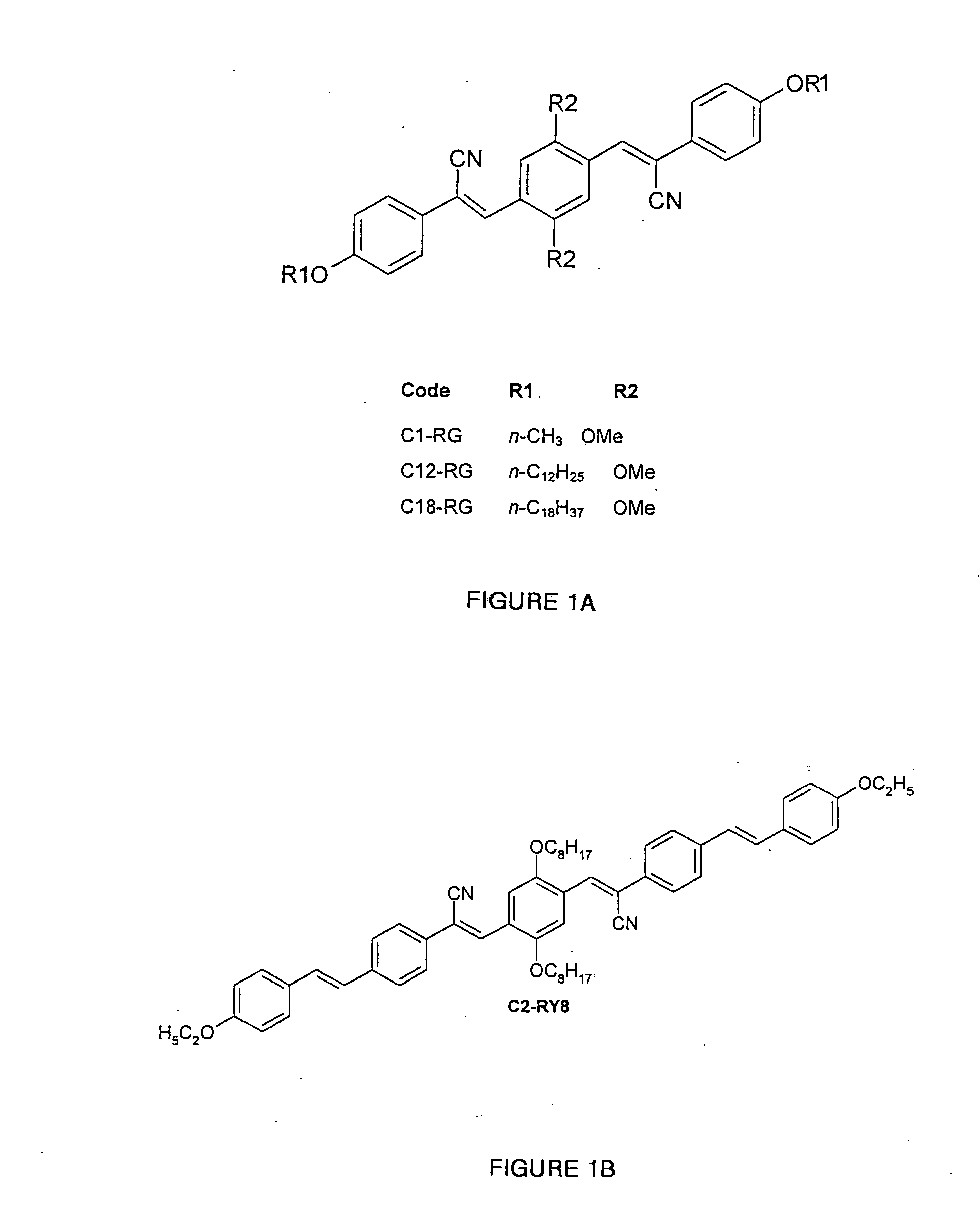
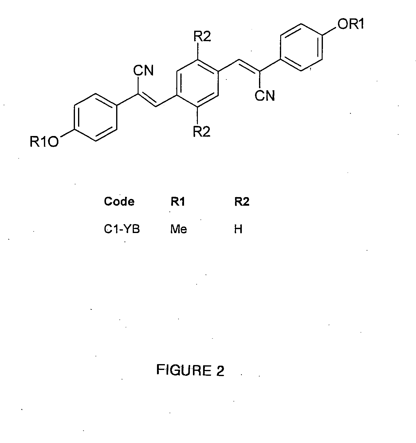
[0080] Aggregachromic dye C1-RG (FIG. 1A) was synthesized according to literature procedures (Lowe, C.; Weder, C. Synthesis 2002, 9, 1185). Aggregachromic dyes C18-RG, C12-RG, C1-RG, and C2-RY8 (FIGS. 1A and 1B) were synthesized as follows: Synthesis of (4-dodecyloxyphenyl)acetonitrile. A suspension of K2CO3 (4.05 g, 29.2 mmol) in dimethylformamide (15 mL) was purged with Ar for 15 minutes, heated to 80° C., and 4-hydroxyphenylacetonitrile (1.47 g, 11.0 mmol) was added. After stirring at 80° C. for 10 minutes, 1-bromododecane (3.54 g, 14.2 mmol) was slowly added and the suspension was stirred at 80° C. under Ar for another 4 hours. After this time a pale yellow precipitate had formed. The reaction was terminated by pouring the suspension into ice-water (150 mL) and CHCl3 (50 mL) was added to dissolve the precipitate. The organic layer was separated off and the aqueous phase was extracted with CHCl3 (3×50 mL). The combined organic layers were washed with H2O and saturated aqueous NaC...

example 1

According to Invention

[0087] Materials and articles comprising between 0.2 and 5% of one of the aggregachromic dyes C18-RG, C12-RG, C2-RY8 or between 2 and 5% C1-RG and one of the polymers of poly(methyl methacrylate) (PMMA), poly(butyl / methyl methacrylate) copolymers, poly(ethylene terephthalate) (PET), and poly(ethylene terephthalate glycol) (PETG) were prepared by feeding the appropriate amounts of dye and the polymer into a recycling, co-rotating twin-screw mini-extruder (DACA Instruments, Santa Barbara, Calif.), mixing for 3-5 minutes at about 200-220° C. (PMMA, poly(butyl / methyl methacrylate) copolymers), 230-250° C. (PETG) and 280° C. (PET, PETG), and subsequent extrusion. Films were prepared by compression-molding the blends at the same temperature at which they were extruded between two aluminum foils that were optionally covered with covered with Kapton films in a Carver press using spacers for approximately 1-3 minutes. The films were immediately quenched after removal f...

example 2

According to Invention

[0094] Materials and articles comprising between 0.2 and 4% of one of the aggregachromic dyes C18-RG and C12-RG and one of the polymers of poly(methyl methacrylate) (PMMA), poly(butyl / methyl methacrylate) copolymers, poly(ethylene terephthalate) (PET), and poly(ethylene terephthalate glycol) (PETG) were prepared by feeding the appropriate amounts of dye and the polymer into a recycling, co-rotating twin-screw mini-extruder (DACA Instruments, Santa Barbara, CA), mixing for 3-5 minutes at about 200-220° C. (PMMA, poly(butyl / methyl methacrylate) copolymers), 230-250° C. (PETG) and 280° C. (PET, PETG), and subsequent extrusion. Films were prepared by compression-molding the blends at the same temperature at which they were extruded between two aluminum foils that were optionally covered with covered with Kapton films in a Carver press using spacers for approximately 1-3 minutes. The films were immediately quenched after removal from the hot press by immersion in a...


PUM

PropertyMeasurementUnit
Fractionaaaaaaaaaa
Fractionaaaaaaaaaa
Fractionaaaaaaaaaa

Abstract

Time temperature indicators are disclosed which comprise at least one carrier material and one aggregachromic indicator dye and which respond to the combined effects of temperature and time with an easily measurable, time-temperature dependent, irreversible, color change. The invention also discloses to methods to produce such time-temperature indicators and materials therefore. Also, the devices disclose methods for determining the time/temperature history.

Description

CROSS REFERENCE [0001] This application claims the benefit of priority under 35 U.S.C. § 119 of U.S. Provisional Application Ser. No. 60 / 758,106 filed on Jan. 11, 2006.STATEMENT OF GOVERNMENT INTEREST [0002] This invention was made with support from the Government under National Science Foundation Contract No. DMI-0428208 through the Division of Design and Manufacturing Innovation. The Government has certain rights in the invention.FIELD OF THE INVENTION [0003] The present invention relates to time-temperature indicators and in particular time-temperature indicators which comprise at least one carrier material and one aggregachromic indicator dye and which respond to the combined effects of temperature and time with an easily measurable, time-temperature dependent, irreversible, color change. The invention also relates to methods to produce such time-temperature indicators. BACKGROUND OF THE INVENTION [0004] Time-temperature indicators (TTI), sometimes also referred to as time-tempe...

Claims


Application Information

Patent Timeline
IPC IPC(8): G02F1/361
CPCC09K9/02
Inventor WEDER, CHRISTOPHKINAMI, MAKICRENSHAW, BRENT
Owner CASE WESTERN RESERVE UNIV
Why Eureka
Try Eureka