Phoshor and light-emitting diode

a light-emitting diode and phoshor technology, applied in the direction of discharge tube luminescnet screen, polycrystalline material growth, crystal growth process, etc., can solve the problem that white light source is unsuitable for a simple illumination device, and achieves convenient adjustment of color rendering, convenient mounting, and efficient emission

Inactive Publication Date: 2007-08-02
MEIJO UNIVERSITY
View PDF3 Cites 48 Cited by
  • Summary
  • Abstract
  • Description
  • Claims
  • Application Information

AI Technical Summary

Benefits of technology

[0039] According to the present invention, it is possible to provide a phosphor capable of controlling an impurity concentration in SiC for efficiently emitting light in a violet-blue-yellow-red visible region through excitation by long-wavelength light or an electron beam in the ultraviolet region or the blue-violet visible region.
[0040] According to the present invention, further, it is possible to provide a white light source allowing easy adjustment of color rendering and easily mountable due to a single light-emitting diode at a low cost. This white light source generates white light therein, whereby change of color shade resulting from an angle of radiation is negligibly small, and the light source is excellent in luminous efficiency.

Problems solved by technology

However, this white light source is unsuitable for a simple illumination device since the device and a driving circuit are complicated to require a high cost.

Method used


Image

  • Phoshor and light-emitting diode
  • Phoshor and light-emitting diode
  • Phoshor and light-emitting diode

Examples


example 1

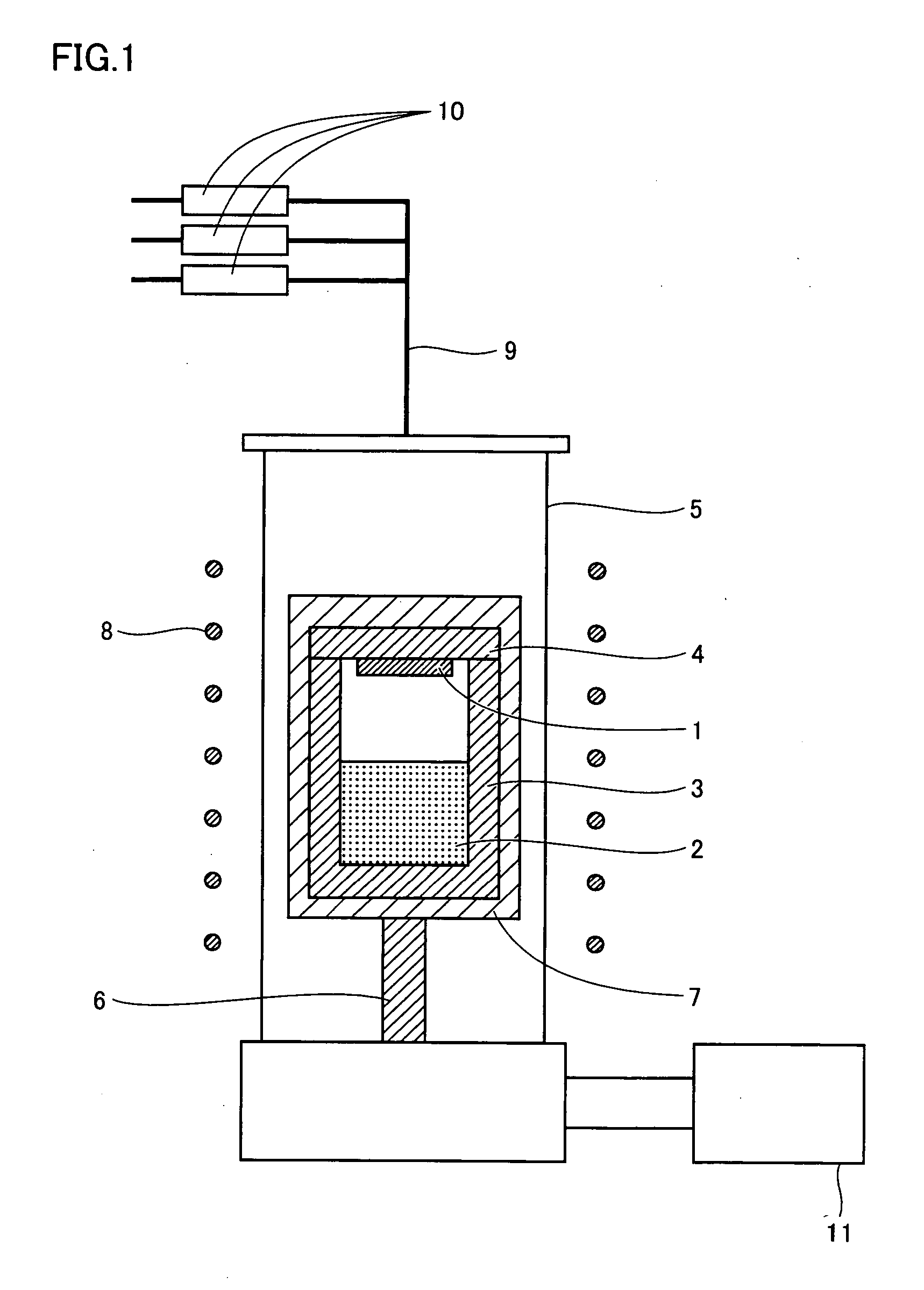
[0099] A phosphor of SiC was prepared by an improved Rayleigh method, as shown in FIG. 1. First, a substrate 1 of single-crystalline SiC serving as a seed crystal was mounted on the inner surface of a lid 4 of a graphite crucible 3. High-purity SiC (JIS particle size: #250) and a B source forming a raw material 2 were mixed with each other, and the mixture was thereafter charged into graphite crucible 3.

[0100] Then, graphite crucible 3 charged with raw material 2 was closed with lid 4 and set in a quartz tube 5 with a support rod 6 of graphite, so that the periphery of graphite crucible 3 was covered with a heat shield 7 of graphite. Ar gas and N2 gas were fed into quartz tube 5 from an introduction tube 9 through a flowmeter 10 as atmosphere gas (flow rate of Ar gas: 1 liter / min). Then, a high-frequency current was fed to a work coil 8, and the temperatures of raw material 2 and substrate 1 were adjusted to reach 2300° C. and 2200° C. respectively.

[0101] Then, the flow rates of t...

example 2

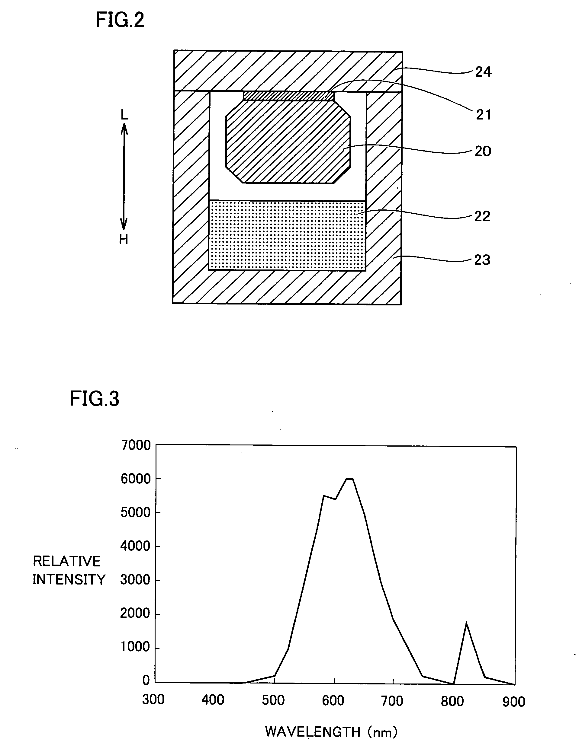
[0105] An SiC crystal was manufactured similarly to Example 1, except that the partial pressure of N2 gas in atmosphere gas in crystal growth was set to 5% and the concentration of simple B with respect to SiC powder was set to 0.5 mol %. The concentrations of N and B in the obtained SiC crystal were 3×10¹⁸ / cm3 and 1×10¹⁷ / cm3 respectively. While the shape of a fluorescence spectrum was similar to that of Example 1, relative intensity of light was improved to substantially three times as compared with the crystal before thermal annealing in Example 1.

example 3

[0106] An SiC crystal was manufactured similarly to Example 1, except that the partial pressure of N2 gas in atmosphere gas in crystal growth was set to 10% and the concentration of simple B with respect to SiC powder was set to 5 mol %. The concentrations of N and B in the obtained SiC crystal were 8×10¹⁸ / cm3 and 5×10¹⁷ / cm3 respectively. While the shape of a fluorescence spectrum was similar to that of Example 1, relative intensity of light was improved to substantially five times as compared with the crystal before thermal annealing in Example 1.


PUM

PropertyMeasurementUnit
peak wavelengthaaaaaaaaaa

Abstract

Disclosed is a phosphor which is excited by a long wavelength light source in the ultraviolet region or blue-violet visible region and mainly emits light in violet-blue-yellow-red visible region. Also disclosed is a low-cost light-emitting diode which is easily mounted and excellent in color rendering properties. This light-emitting diode does not have much color change due to radiation angle. A phosphor composed of SiC is characterized in that it is excited by an outside light source for emitting light and doped with N and at least one of B and Al.

Description

TECHNICAL FIELD [0001] The present invention relates to a phosphor of SiC excited by an electromagnetic wave such as an electron beam, an X-ray, an ultraviolet ray or a blue-violet visible ray for emitting light and a method of manufacturing the same as well as a substrate and powder for a semiconductor consisting of such a phosphor. The present invention further relates to a light-emitting diode comprising a group III nitride semiconductor expected for future popularization as a new solid illuminating device. BACKGROUND ART [0002] A PDP panel emitting light by exciting a phosphor with a vacuum ultraviolet ray radiated by rare gas discharge is actively developed. The PDP panel is formed by a large number of display cells arranged in the form of a matrix, and each display cell is provided with an ignition electrode. The inner part thereof is coated with a phosphor, to seal rare gas such as He—Xe or Ne−Xe. When a voltage is applied to the ignition electrode, a vacuum ultraviolet ray i...

Claims


Application Information

Patent Timeline
Patent Type & Authority Applications(United States)
IPC IPC(8): H01J1/62H01J63/04C09K11/08C09K11/59C09K11/62C09K11/63C09K11/65H01L21/203H01L33/50
CPCC09K11/0883C09K11/59C30B29/36H01L33/502C30B23/00C09K11/63H01L2224/16145H01L2224/45144H01L2224/48091H01L2224/49107H01L2224/8592H01L2924/00014H01L2924/00C09K11/0838C09K11/62C09K11/655H01L21/203H01L33/00
Inventor KINOSHITA, HIROYUKISHIOMI, HIROMUSASAKI, MAKOLOHAYASHI, TOSHIHIKOAMANO, HIROSHIKAMIYAMA, SATOSHITWAYA, MOTOAKIAKASAKI, ISAMU
Owner MEIJO UNIVERSITY
Why Eureka
Try Eureka