Aspiration catheter

a technology of aspiration catheter and lumen, which is applied in the field of catheters, can solve the problems of long recovery time, long recovery time, and slow flow or no flow, and achieve the effects of preventing thrombosis, increasing length, and small cross-sectional area of aspiration lumen 100

Active Publication Date: 2007-08-16
KANEKA CORP
View PDF19 Cites 22 Cited by
  • Summary
  • Abstract
  • Description
  • Claims
  • Application Information

AI Technical Summary

Benefits of technology

[0048] The aspiration catheter of the present invention is characterized by the inclusion of the detachable core wire 101 as described above. The mechanism for allowing the core wire 101 to be detachable is not particularly limited. However, in consideration of operationality during the detachment of the core wire 101, preferably, a connector 107 is fixed on the proximal end of the core wire 101, and the connector 107 is mounted to the proximal end of the hub 106 in a detachable manner. The method for fixing between the proximal end of the core wire 101 and the connector 107 does not restrict the advantageous effects of the present invention at all, and fixing may be performed using an adhesive or the like. In such a case, the type of adhesive used is not particularly limited. The method for connecting the connector 107 to the proximal end of the hub 106 is not limited as long as the connector 107 is detachable. In one preferred embodiment, the distal end of the hub 106 is formed as a female Luer adaptor and the connector 107 is formed as a male Luer adaptor. Thereby, the core wire 101 can be reliably and easily detached. Furthermore, by forming the proximal end of the hub 106 as a female Luer adaptor, it is also possible to simply apply a negative pressure to the aspiration lumen 100 using a syringe or the like.
[0049] As described above, when the connector 107 is fixed on the proximal end of the core wire 101 and the connector 107 is mounted to the proximal end of the hub 106 in a detachable manner, it is possible to achieve a structure in which the aspiration lumen 100 is flushed through the connector 107. When the aspiration catheter of the present invention is used, it is necessary to flush the aspiration lumen 100 with a suitable solution, such as a solution of physiological heparinized saline, before insertion into the body. Flushing prevents thrombus formation when the aspiration catheter is inserted into the body, in particular, the blood vessels. Flushing is usually performed using a syringe. Consequently, by forming the proximal end of the connector 107 as a female Luer adaptor, it is possible to perform flushing with the core wire 101 being mounted, and it is possible to insert the aspiration catheter into the body promptly after flushing to start treatment.
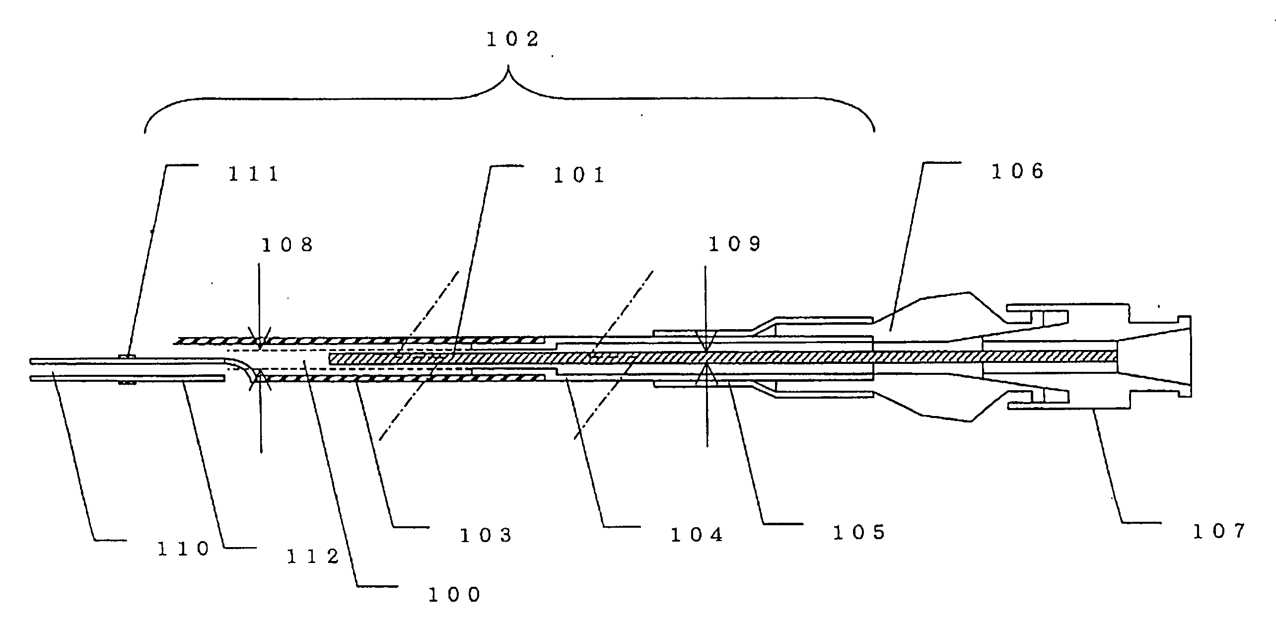
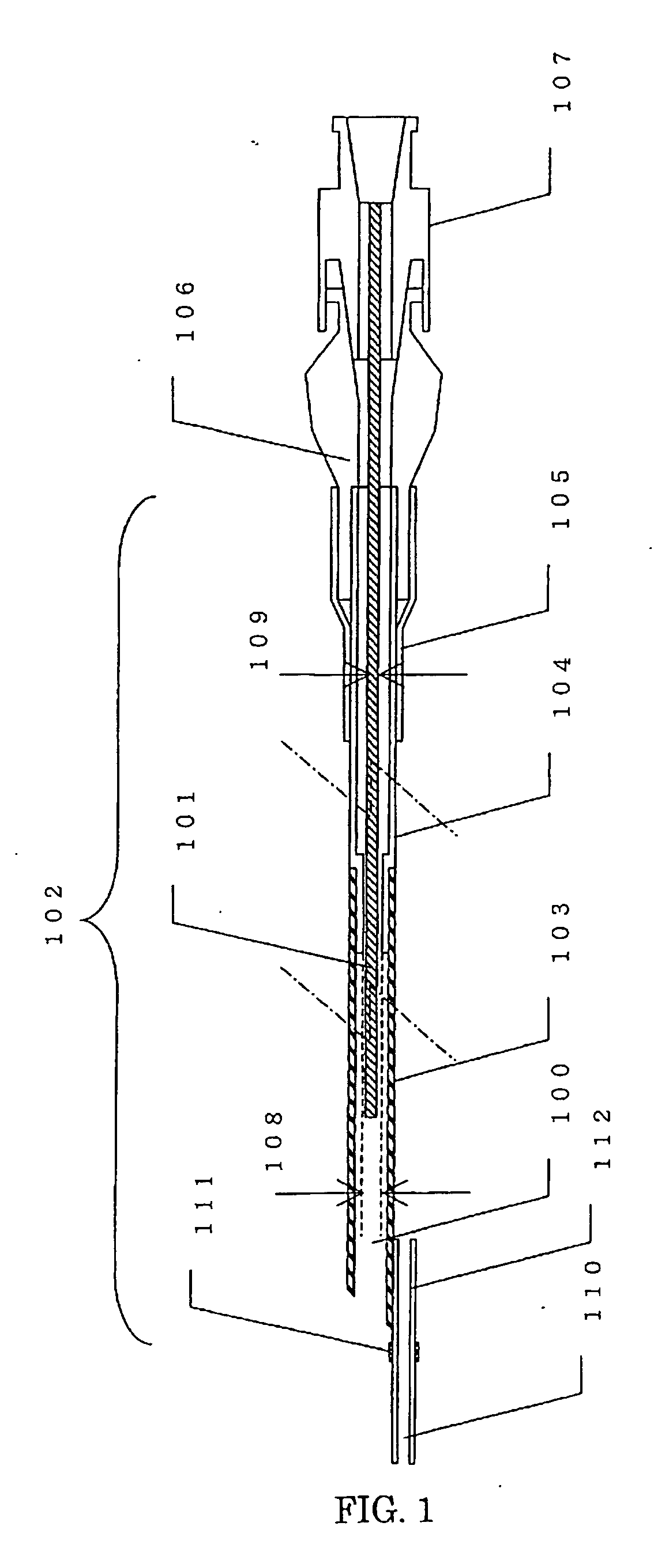
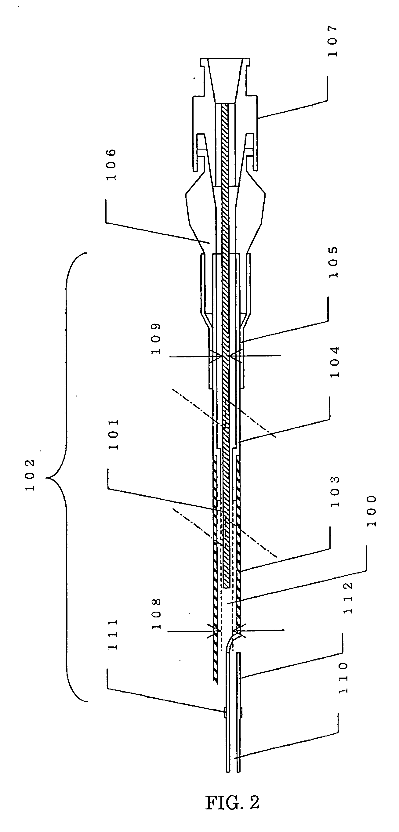
[0050] The positional relationship between the guidewire lumen 110 and the aspiration lumen 100 does not restrict the advantageous effects of the present invention at all. As shown in FIG. 1, the guidewire lumen 110 and the aspiration lumen 100 may be disposed independently of each other. As shown in FIG. 2, the guidewire lumen 110 may be partially disposed inside the aspiration lumen 100. Alternatively, the guidewire lumen 110 may be entirely disposed inside the aspiration lumen 100. However, when the guidewire lumen 110 is partially or entirely disposed inside the aspiration lumen 100, the cross-sectional area of the aspiration lumen 100 is smaller compared with the case in which the guidewire lumen 110 and the aspiration lumen 100 are disposed independently of each other. In particular, an increase in the length in the longitudinal direction of the portion of the guidewire lumen 110 disposed inside the aspiration lumen 100 leads to a decrease in the amount of aspiration. Therefore, the length of the portion of the guidewire lumen 110 disposed inside the aspiration lumen 100 is preferably as small as possible. On the other hand, when the guidewire lumen 110 and the aspiration lumen 100 are disposed independently of each other, there is an increased risk that the guidewire shaft 112 will be separated from the distal shaft 103 when the aspiration catheter is inserted or withdrawn along a guidewire. It is also possible to reinforce the joint between the guidewire shaft 112 and the distal shaft 103 using another component. In such a case, however, the outer diameter of the joint significantly increases. As described above, the aspiration ability and safety of the catheter greatly depend on the positional relationship between the guidewire lumen 110 and the aspiration lumen 100. Therefore, it is obvious to those skilled in the art that the aspiration catheter can be appropriately designed in consideration of the target site to be treated, method for use, required amount of aspiration, substance subjected to aspiration, etc.
[0051] With respect to the material for the guidewire shaft 112, in order to secure good slidability with a guidewire, at least the inner surface thereof is preferably composed of a polyolefin, in particular, a polyethylene.
[0052] The method for bonding between the distal shaft 103 and the guidewire shaft 112 does not restrict the advantageous effects of the present invention at all. Namely, if the distal shaft 103 and the guidewire shaft 112 are composed of materials that can be welded to each other, bonding can be performed by welding. Alternatively, if the distal shaft 103 and the guidewire shaft 112 are composed of materials that cannot exhibit sufficient bonding strength when welded, bonding may be performed using an adhesive. In such a case, the chemical species in the adhesive used is not particularly limited. For example, a cyanoacrylate, urethane, epoxy, or silicone adhesive is preferably used. The curing mechanism of the adhesive is also not particularly limited. For example, a moisture-curing, two-part curing, or photo-curable adhesive is suitably used. If the distal shaft 103 and the guidewire shaft 112 are composed of materials having poor adhesion properties, surface treatment may be performed, for example, by oxygen plasma or corona discharge, or using a silane coupling agent, before bonding.
[0053] Preferably, the distal end of the core wire 101 recedes from the distal end of the aspiration lumen 100 in the proximal direction. If the distal end of the core wire 101 protrudes from the distal end of the aspiration lumen 100, there is a high risk of internal injuries during insertion. Furthermore, after aspiration treatment is performed with the core wire 101 being dismounted, when it becomes necessary to move the aspiration catheter to treat another site and the core wire 101 is mounted inside the aspiration lumen 100, internal injuries due to the core wire 101 are highly likely to occur.

Problems solved by technology

However, when occlusion is caused by thrombi in the blood vessel, if the occluded area is dilated by the balloon catheter, there may be a possibility that the thrombi are detached from the inner wall of the blood vessel to occlude peripheral vessels downstream.
When peripheral vessels are blocked as described above, even if the occluded area or narrowed area is dilated, blood is prevented from flowing into the peripheries, resulting in slow-flow or no-reflow.
When such a situation arises, in the coronary artery or the like, it is general practice to wait and see if the blood flow is recovered, but a long recovery time is required.
In either case, a long recovery time is still required.
Consequently, in order to enhance the transmission of power in the catheter shaft, the entire catheter shaft must be composed of a relatively hard material, often resulting in difficulty in advancing the catheter to the target site in the blood vessel.
Furthermore, since a negative pressure must be applied from the proximal end of the catheter simultaneously with the application of mechanical power, a large-scale device is required, and thus this method has not become widely used.
However, the cross-sectional area of the aspiration lumen for aspiration is not sufficiently secured, and only catheters having low aspiration capability are available.
Namely, since a guidewire lumen tracking the guidewire is provided in the aspiration lumen, it is not possible to secure a sufficient aspiration lumen.
Consequently, the outer diameter of the guiding catheter used together increases so that a sufficient inner diameter is secured, resulting in an enormous burden to the patient.
In addition, since any of the guidewire lumens described above usually has a length of about 30 cm from the tip of the aspiration catheter, the entire catheter shaft lacks flexibility, resulting in poor insertability into tortuous blood vessels.
However, when a catheter having such a structure is used as an aspiration catheter in a conventional PTCA procedure, it is not possible to advance the catheter to an affected site over a guidewire, and low operationality has been pointed out as a problem.

Method used


Image

  • Aspiration catheter
  • Aspiration catheter
  • Aspiration catheter

Examples


examples

[0073] Examples and comparative examples of the present invention will be described in detail below.

example 1

[0074] As a proximal shaft, a polyimide tube with an outer diameter of 1.30 mm, an inner diameter of 1.10 mm, and a length of 1,100 mm was formed by dip forming using a polyamic acid varnish. As a distal shaft, a tube with an outer diameter of 1.30 mm, an inner diameter of 1.00 mm, and a length of 300 mm was formed by extrusion molding of low-density polyethylene (LF480M, Japan Polychem Corporation). The diameter of one end of the proximal shaft was reduced by thermal drawing. The portion in which the diameter was reduced was inserted into the distal shaft and fixed by bonding using a two-part curing urethane adhesive (Nipporan 4235 / Coronate 4403, Nippon Polyurethane Industry Co., Ltd.), and a main shaft was thereby obtained. Since the distal shaft was composed of a material with poor adhesion properties, oxygen plasma treatment was performed before bonding.

[0075] The tip of the distal shaft was obliquely cut so that the length L1 in the longitudinal direction of the catheter was 2...

example 2

[0078] An aspiration catheter was produced as in Example 1 except that a straight wire composed of SUS304 alloy steel with an outer diameter of 0.715 mm was used as a core wire.


PUM


Abstract

There has been a demand for an aspiration catheter which has a sufficient amount of aspiration, which is sufficiently flexible to satisfactorily track tortuous blood vessels, in which the possibility of kinking of a catheter shaft is decreased when the aspiration catheter is inserted into a guiding catheter from outside of the body, and in which good operationality is achieved. An aspiration catheter of the present invention includes an aspiration lumen for removing a substance by aspiration, the aspiration lumen extending to a hub provided at the proximal end of the catheter; and a detachable core wire disposed in the aspiration lumen.

Description

TECHNICAL FIELD [0001] The present invention relates to a catheter percutaneously and transluminally introduced into the body to remove by aspiration a substance present in the body, and in particular, the invention relates to an aspiration catheter for removing by aspiration thrombi formed in the internal blood vessels and debris, such as atheromas, released in the blood vessels, by applying a negative pressure from the proximal end of the catheter. BACKGROUND ART [0002] Conventionally, when stenosis or occlusion occurs in vessels, such as blood vessels, and when blood vessels are blocked by thrombi, angioplasties (e.g., PTA: Percutaneous Transluminal Angioplasty and PTCA: Percutaneous Transluminal Coronary Angioplasty) are commonly performed in order to dilate narrowed areas or reopen occluded areas of blood vessels so that blood flow in the peripheries of blood vessels is improved. Many angioplasties have been performed in many medical institutions. Furthermore, in recent years, ...

Claims


Application Information

Patent Timeline
Patent Type & Authority Applications(United States)
IPC IPC(8): A61M25/00A61M25/01A61M29/02
CPCA61M25/0023A61M25/003A61M25/0043A61M2025/1056A61M2025/0063A61M2025/0183A61M25/0102A61M1/00A61M25/01A61M25/09
Inventor NISHIDE, TAKUJIHASHIBA, MASATOMIKI, SHOGO
Owner KANEKA CORP
Why Eureka
Try Eureka