
Semiconductor device and method of manufacturing the same

a semiconductor and semiconductor technology, applied in the field of semiconductor devices and manufacturing the same, can solve the problems of difficult to manufacture a tft, difficult to form a channel formation region of every tft in the pixel portion within one crystal mass, and large size of crystal grains obtained by this technique, so as to reduce fluctuation and increase current

Inactive Publication Date: 2007-08-23
SEMICON ENERGY LAB CO LTD
View PDF34 Cites 0 Cited by
  • Summary
  • Abstract
  • Description
  • Claims
  • Application Information

AI Technical Summary

Benefits of technology

[0025] An object of the present invention is to provide measures for obtaining a TFT with its channel formation region which has a plurality of uniform crystal masses in size. The present invention can provide a semiconductor device which has very little fluctuation in TFT characteristics, and can prevent the fluctuation from being a problem when display with higher definition is demanded in future.
[0026] Furthermore, the present invention is capable of controlling the grain size by adjusting the energy density of laser light before the heat treatment. Accordingly, the size of a crystal mass can be appropriately adjusted to suit the pixel size or the size of a channel formation region. Thus, the present invention prevents the fluctuation from being a problem when the channel formation region becomes more minute in size in future.
[0028] According to the measures of the present invention, crystallization can be achieved with a smaller dose of metal element than that in the technique described in the above publication even when the temperature and time of the heat treatment are the same as those in the technique described in the publication above. The metal element for accelerating crystallization is desirably removed by a gettering technique or the like after crystallization and therefore crystallization with a smaller dose of metal element is better. As the thickness of an amorphous silicon film to be crystallized is increased, the time of the heat treatment has to be prolonged, the temperature of the heat treatment has to be set higher, or a larger dose of metal element is required for sufficient crystallization in prior art. On the other hand, the present invention can achieve crystallization without changing heat treatment conditions even when the thickness of an amorphous semiconductor film to be crystallized is increased. In short, the present invention can crystallize a larger area of amorphous semiconductor film in a shorter time than prior art.
[0040] As has been described, it makes an impurity contained in the semiconductor film (an element which has a high diffusion constant or a high degree of solid solution in the semiconductor film, hydrogen, for example) diffuse in the solid film for performing improved crystallization later to irradiate laser light with an energy which is not large enough to melt a semiconductor film with an amorphous structure before crystallization. When a semiconductor film with a uniform amorphous structure, obtained by irradiating laser light with an energy which is not large enough to melt the semiconductor film, is crystallized, a semiconductor film with a uniform crystal structure can be obtained. Accordingly, TFTs using as their active layers this semiconductor film with a crystal structure are uniform in characteristics to reduce uneven display and fluctuation in luminance.
[0043] Selective irradiation of laser light (with energy which is not large enough to melt a semiconductor film) makes it possible to form different TFTs so as to suit different circuits. For instance, regions for forming TFTs used for a circuit in which the fluctuation matters, such as a pixel TFT used as a switching element and a TFT of an analog switch circuit, are irradiated with laser light (with energy which is not large enough to melt a semiconductor film) whereas regions for forming TFTs used for a circuit in which an increase in ON current matters more than reduced fluctuation, such as a TFT of a buffer circuit, are not irradiated with the laser light. Then, crystallization is performed through heat treatment to selectively form regions where crystal grains are small and the fluctuation is small (regions irradiated with the laser light) and regions where crystal grains are large (regions that are not irradiated with light).

Problems solved by technology

Crystal grains obtained by this technique are very large in size.
However, with the technique of the above publication, crystal masses are formed at random and it is difficult to manufacture a TFT with its channel formation region placed within one of the randomly-formed crystal masses.
Accordingly, it is also difficult to form a channel formation region of every TFT in the pixel portion within one crystal mass.
If there is a fluctuation in electric characteristics among the TFTs placed in the pixel portion, voltages applied to the respective pixel electrodes are fluctuated and the amount of light transmitted is then fluctuated, to result in uneven display to the eyes of an observer.
Although the fluctuation is in an acceptable range and does not cause a problem at present, it is conceivable that the fluctuation is a very serious problem as the pixel size is more minute to obtain an image with higher definition in future.
With the reduction in size of a channel formation region (channel length and channel width) as wall as the upcoming reduction in the width of a wiring line, it is unavoidable that a TFT has its channel formation region at a boundary between crystal masses.
Despite several attempts, there have not been found the optimum measure to form a crystalline silicon film which has a uniform grain size at a process temperature equal to or lower than the distortion point of glass substrate, namely, 600° C.
It is difficult to obtain a highly uniform crystalline silicon film and high mobility at the same time in prior art.
It is also difficult to manufacture a TFT at a process temperature equal to or lower than 600° C. in prior art.
However, TFTs formed from polysilicon easily fluctuate in characteristics due to defects in grain boundaries.

Method used


Image

  • Semiconductor device and method of manufacturing the same
  • Semiconductor device and method of manufacturing the same
  • Semiconductor device and method of manufacturing the same

Examples


experiment 1

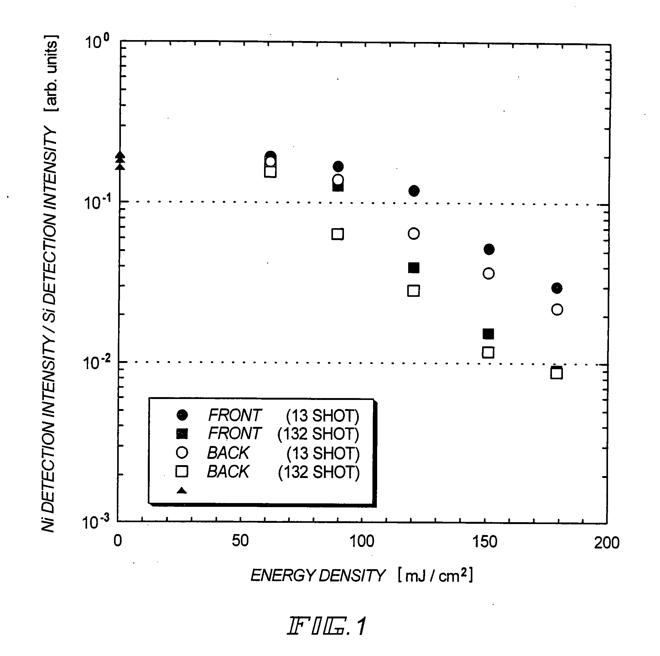
[0079] First, a silicon oxide film with a thickness of 280 nm and an amorphous silicon film with a thickness of 69 nm are formed by reduced pressure thermal CVD and layered on a quartz substrate and a nickel acetate aqueous solution (5 ppm) is applied thereto to prepare a sample. While laser light conditions are varied (including the energy density and the number of shots), samples are irradiated with laser light. Then, the nickel detection intensity and the silicon detection intensity on the surfaces are measured by TXRF (total reflection X-ray fluorescence) to calculate the ratio of the nickel detection intensity to the silicon detection intensity. Experiment 1 is an experiment for examining the presence or absence of a change in nickel concentration immediately after irradiating the laser light.

[0080]FIG. 1 shows the results of Experiment 1. In FIG. 1, samples irradiated with excimer laser light (energy density: 60 mJ / cm2, 90 mJ / cm2, 120 mJ / cm2, 150 mJ / cm2, 180 mJ / cm2) of 132 sh...

experiment 2

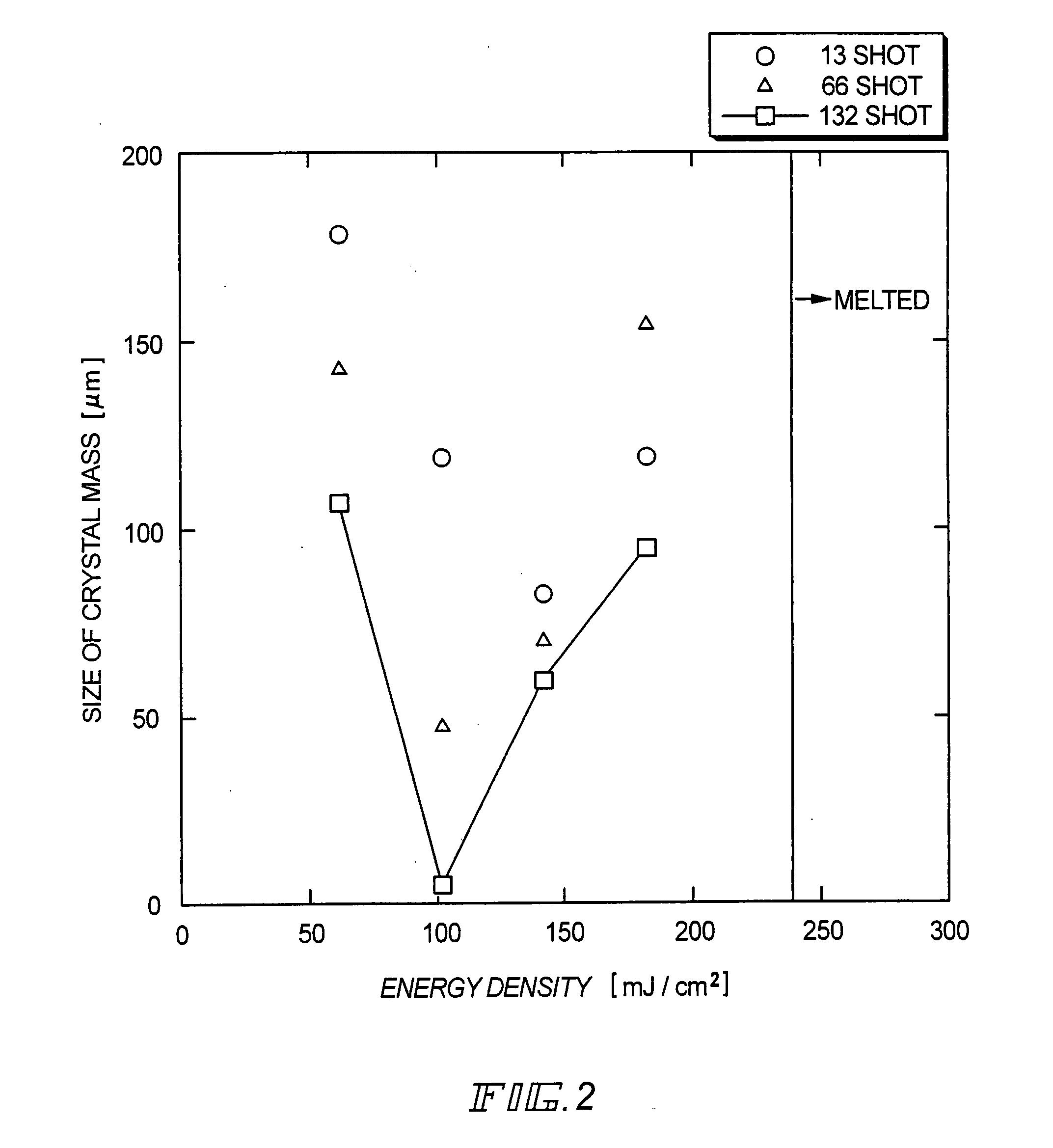
[0081] The samples irradiated with laser light from the back side in Experiment 1 are subjected to heat treatment (heat treatment at 450° C. for an hour which is followed by heat treatment at 600° C. for twelve hours) for crystallization. The samples are then observed through an optical microscope to measure sizes of crystal masses. Experiment 2 is an experiment for examining the relation between the size of the crystal mass and the energy density in the case where irradiation of laser light from the back side precedes heat treatment for crystallization.

[0082]FIG. 2 shows the results of Experiment 2. In FIG. 2, samples irradiated with excimer laser light (energy density: 60 mJ / cm2, 90 mJ / cm2, 120 mJ / cm2, 150 mJ / cm2, 180 mJ / cm2) of 132 shots from the back side of the substrate are plotted and indicated by □. Samples irradiated with excimer laser light (energy density: 60 mJ / cm2, 90 mJ / cm2, 120 mJ / cm2, 150 mJ / cm2, 180 mJ / cm2) of 13 shots from the back side of the substrate are plotte...

embodiment 1

[0098] Embodiment 1 describes an example of manufacturing a TFT from an amorphous semiconductor film obtained by reduced pressure thermal CVD on a quartz substrate (1.1 mm in thickness). The description is given with reference to FIGS. 4A to 4G First, an amorphous silicon film 101 with a thickness of 50 nm and a silicon oxide film 102 with a thickness of 50 nm are formed on each side of a quartz substrate 100 by reduced pressure thermal CVD (FIG. 4A).

[0099] A resist film 103 is formed next in order to remove the amorphous silicon film and silicon oxide film formed on the back side of the substrate. The silicon oxide film on the back side is removed by a solution containing fluoric acid, and the amorphous silicon film on the back side is removed by a mixture gas of SF6 and He (FIG. 4A).

[0100] Next, the resist film 103 is removed and the silicon oxide film 102 on the front side is removed. After washing the substrate with diluted fluoric acid, an oxide film (not shown) is formed by ...


PUM

PropertyMeasurementUnit
sizeaaaaaaaaaa
sizeaaaaaaaaaa
sizesaaaaaaaaaa

Abstract

The sizes of crystal masses are made to be a uniform in a crystalline silicon film obtained by a thermal crystallization method in which a metal element is used. An amorphous silicon film to be crystallized is doped with a metal element that accelerates crystallization, and then irradiated with laser light (with an energy which is not large enough to melt the film and which is large enough to allow the metal element to diffuse in the solid silicon film) from the back side of a light-transmissive substrate. Thereafter, heat treatment is performed to obtain a crystalline silicon film. Thus crystal masses in the crystalline silicon film can have a uniform size and the problem of fluctuation between TFTs can be solved.

Description

BACKGROUND OF THE INVENTION [0001] This application is a divisional of prior application Ser. No. 10 / 141,451 filed May 8, 2002. [0002] 1. Field of the Invention [0003] The present invention relates to a semiconductor device which has a circuit composed of a thin film transistor (hereinafter referred to as TFT), and to a method of manufacturing the semiconductor device. For instance, the present invention relates to an electro-optical device represented by a liquid crystal display panel, and to electronic equipment which has such electro-optical device as its component. [0004] In this specification, the term semiconductor device refers to a device in general that utilizes semiconductor characteristics to function, and electro-optical devices, light emitting devices, semiconductor circuits, and electronic equipment are all semiconductor devices. [0005] 2. Description of the Related Art [0006] In recent years, development of a semiconductor device has been advanced, which has a large a...

Claims


Application Information

Patent Timeline
Patent Type & Authority Applications(United States)
IPC IPC(8): H01L21/786G02F1/1368G09F9/00G09F9/30H01L21/20H01L21/3205H01L21/336H01L21/77H01L21/84H01L23/52H01L27/12H01L29/04H01L29/423H01L29/43H01L29/49H01L29/786H01L51/50H01S3/00H05B33/10
CPCH01L27/12H01L29/04H01L29/66757H01L29/66765H01L27/1277H01L29/78645H01L29/78675H01L29/78678H01L29/78621
Inventor KASAHARA, KENJIMAEKAWA, SHINJISHIBATA, HIROSHIMIYAIRI, HIDEKAZU
Owner SEMICON ENERGY LAB CO LTD
Learn More