[0007] A further object of the present invention is to provide an optical fiber component package that will avoid damage to the optical fiber device due to mechanical stresses.
[0012] The same concerns apply to the
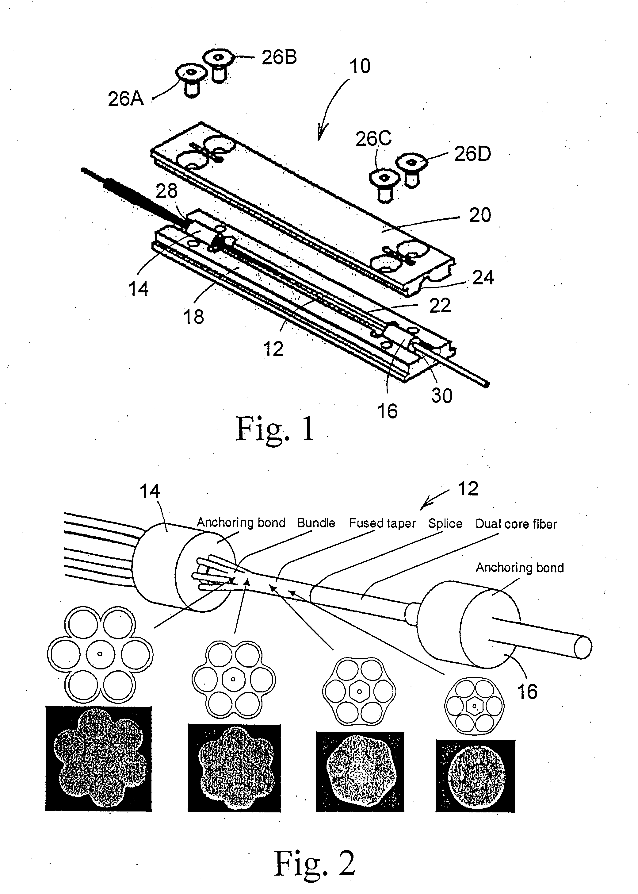
signal-carrying fiber, especially in the case of large mode area fibers, where low numerical apertures and large V numbers make splicing an important source of
modal degradation. Increased LP01 loss not only generates heat loads, but also can result in a non-thermally driven failure mode. As more interfering
modes are excited,
gain instabilities can lead to the generation of intense pulses that will exceed the material breakdown threshold of glass, resulting in destruction of the core, typically in the regions of smallest mode
diameter. It is not the purpose of a packaging solution to solve this issue, however, the coupler package should preserve
modal quality during
assembly and subsequently in all conditions of use, including
laser power cycling and ambient
temperature cycling.
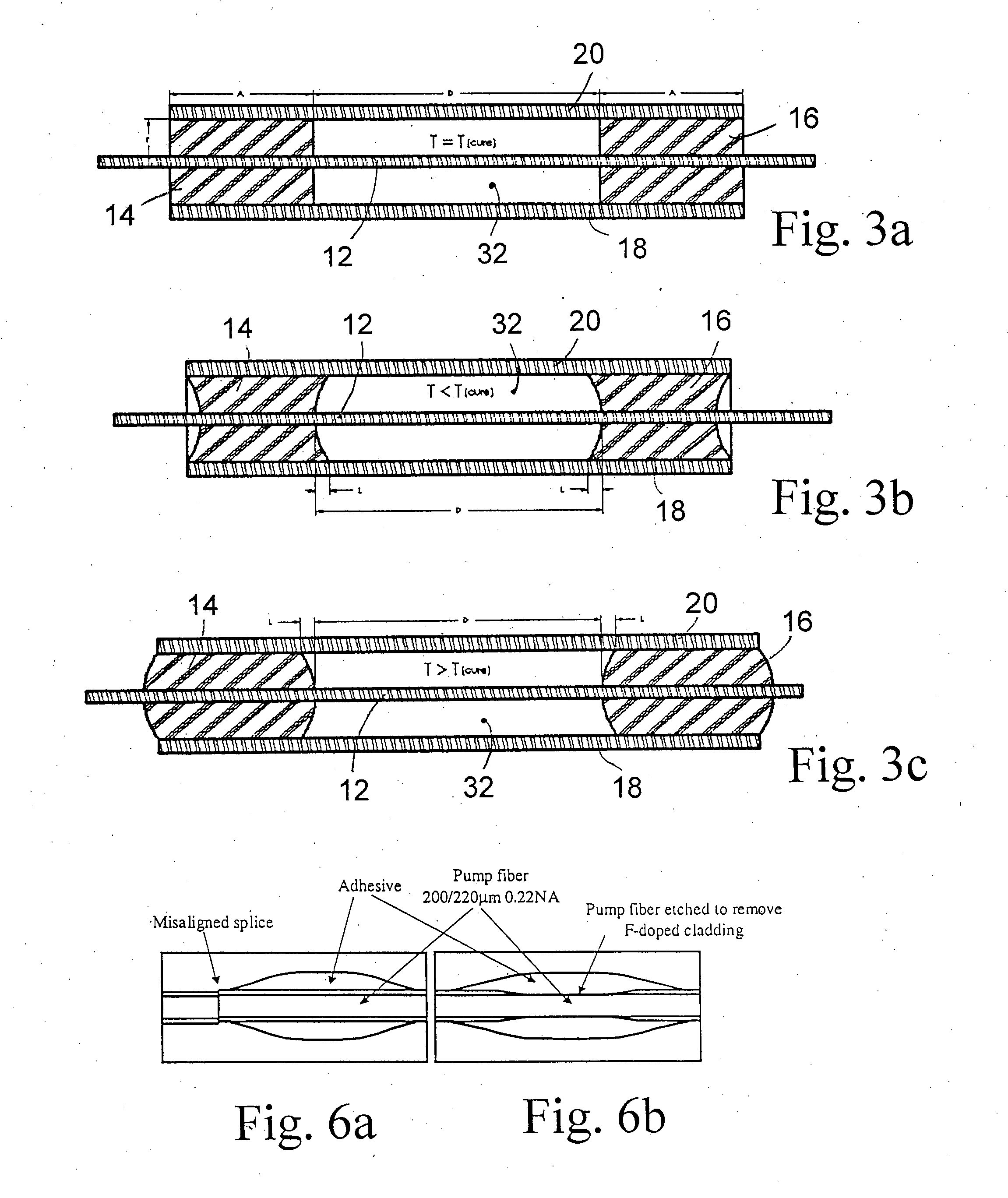
[0017] Equation 4 predicts a longitudinal profile where a peak is present some distance away from the edges of the bondline. It is important to locate this point in order to properly establish the
maximum temperature reached during operation. In order to corroborate the model, samples were instrumented to provide temperature-mapping capability inside a fully enclosed package.
Capillary tubing transecting the adhesive bond in the radial and longitudinal axis were introduced to allow
high reflectivity Bragg gratings to be positioned for profiling. To produce a well-controlled optical
loss function, a length of pump fiber was stripped and etched in
hydrofluoric acid to
expose its core to mode stripping from the adhesive. A match was shown between the fitted theoretical profile and the temperature reading from the Bragg. In the radial profile, most heat is generated close to the fiber, probably because the refracted
signal has a strong forward directionality. This measurement also confirms that the sidewalls of the package are indeed acting as heatsinks, the distribution matching closely the package sidewall
diameter of 3 mm. This analysis indicates that the best strategy to decrease
temperature elevation in the package is to control and preferably to minimize the length and
diameter of the adhesive, select an adhesive with good transparency and make it contact a packaging material with good
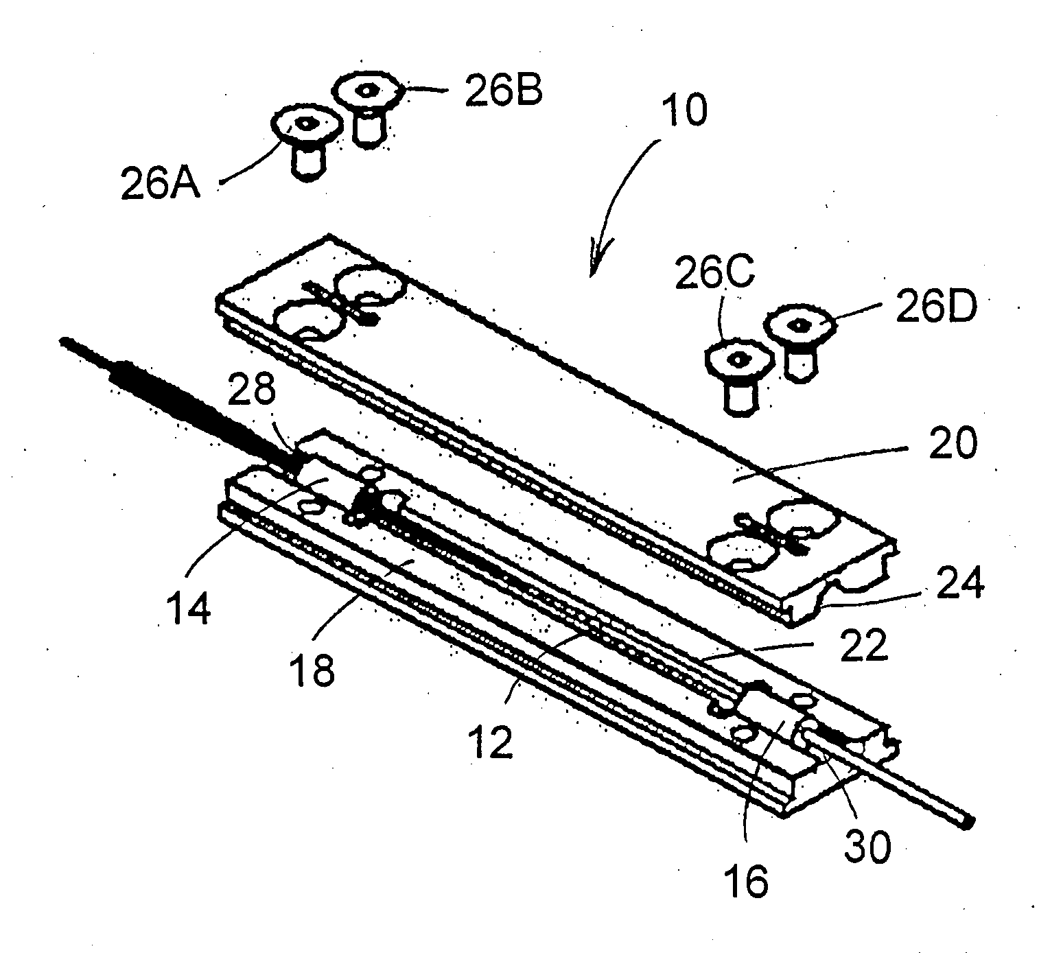
thermal conductivity. Also, the packaging material should be such as to compensate for any variation of the adhesive bond at each end of the package, due to temperature variation, so as to prevent damage to the optical device by mechanical stresses that may otherwise be produced.
[0023] The packaging substrate should preferably have a high
thermal conductivity and an
absorption capacity such as to absorb essentially
all optical loss emanating from the optical fiber device when it is in operation. It may consist of
metal or
alloy (e.g. CuW or CuMo), or a
metal composite (e.g. AlSi), or an advanced
composite material (pyrolated
graphite), or a
ceramic (e.g. A1N), or it can be a combination of two materials in a bi-material arrangement (e.g.
Invar or
Kovar with inserts of Cu, Ag or Al), or a combination of the above with a highly conductive layer (e.g. electroplated, hot dipped, thin film or foil). Normally, the thermal
conductivity should be at least 100 w / mk (watts / meter-
kelvin), and preferably it should be higher than 130 w / mk. Normally, the packaging is opaque because this allows the spurious optical
signal to be directly absorbed and dissipated, and thus offers an efficient heat extraction and protection against
exposure to damaging
optical power.
[0027] The surface of the inner walls of the packaging substrate may be treated to minimize reflections and maximize effective dissipative power of the package. This can be done by abrasion, oxidation or thin
film coating or a combination thereof. The finish of the outside surfaces is preferably designed to maximize thermal
conductivity. The package produced is preferably flat and rectangular to allow efficient
thermal contact when mounting to a flat surface; Also, grooved channels on each side of the package wall are normally provided to allow clamping down with a variety of fasteners and a precise positioning of the component into a complete
assembly, providing means to finely adjust its position with respect to other components in the
assembly. This also allows CTE mismatches between package and mounting surface to be resolved through pistonning. Finally,
strain relief shapes may be machined into the ends of the channels to avoid the use of more conventional elastomeric boots, which may be susceptible to degradation.

