Methods for Preparing and Functionalizing Nanoparticles

a nanoparticle and functionalization technology, applied in the field of chemistry and biology, can solve the problems of short lifetime, large spectral features, photobleaching, and potential cell toxicity, and achieve the effect of reducing or eliminating

Inactive Publication Date: 2007-09-13
RGT UNIV OF CALIFORNIA
View PDF10 Cites 27 Cited by
  • Summary
  • Abstract
  • Description
  • Claims
  • Application Information

AI Technical Summary

Benefits of technology

[0019] In another aspect the invention includes a method for functionalizing nanoparticles by mixing a functionalizing agent vapor with a humidified aerosol comprising the nanoparticles. Water molecules present on the surface of the nanoparticles facilitates the coating reaction, which results in a layer of free reactive chemical groups on the surface of the particles. The reactive groups permit the particles to be conjugated with, e.g., molecules of biological interest such as proteins, carbohydrates, and nucleic acids. The aerosol containing the particles is introduced in a reaction chamber in which it joins a steady flow of functionalizing agent vapor that may optionally be entrained in an inert carrier gas. The functionalization reaction tales place on the surface of the particles while they are suspended in the reaction chamber. These methods largely avoid the agglomeration problems encountered with liquid-phase functionalization reactions and also greatly reduce or eliminate the need of post-functionalization washing of the particles.

Problems solved by technology

The labels are often organic dyes that give rise to the usual problems of broad spectral features, short lifetime, photobleaching, and potential toxicity to cells.
A further drawback of fluorescent dye technology is that the conjugation of dye molecules to biological molecules requires a chemistry that generally is unique to each pair of molecules.
However, quantum dot technology still is in its infancy, and is plagued by many problems including difficulties associated with reproducible manufacture, coating, and derivatization of quantum dot materials.
In addition, although the quantum yield of an individual quantum dot is high, the actual fluorescence intensity of each tiny dot is low.
Grouping multiple quantum dots into larger particles is one approach for increasing the fluorescence intensity, but this nascent technology still suffers from drawbacks including difficulties in generating and maintaining uniform particle size distributions.
Wider application of quantum dot technology therefore has been limited by the difficulties referred to above.
However, this chelation chemistry often is expensive and complex, and so application of rare-earth chelation technology also has been limited to date.
However, Eu2O3 and other nanoparticles are easily dissolved by acid during activation and conjugation, thereby losing their desirable properties.
In addition, nanoparticles lack reactive groups that allow them to be easily derivatized and linked to analytes and other reagents, thus increasing the difficulty associated with using nanoparticles as labeling reagents for the study of biological and other molecules.
However, coating with silica and alumina may increase the particle size, thereby compromising the advantageous properties of nanoparticles that render them suitable as labeling reagents.
U.S. Pat. No. 6,773,812 describes particles having magnetic and light emitting properties, but the light-emitting properties of those particles are derived from conventional dyes such as fluorescent dyes and so suffer from the associated disadvantages of photobleaching, small Stokes shifts, and short lifetimes.

Method used


Image

  • Methods for Preparing and Functionalizing Nanoparticles
  • Methods for Preparing and Functionalizing Nanoparticles
  • Methods for Preparing and Functionalizing Nanoparticles

Examples


example 1

Gas-Phase Synthesis of Eu:Na:Si Nanoparticles

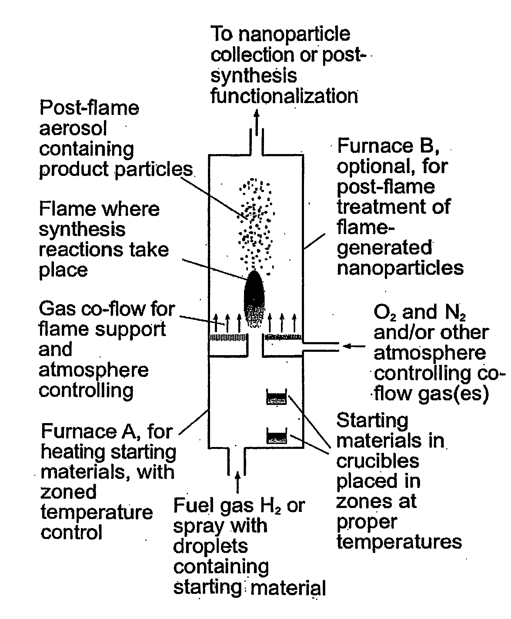
[0060] 50 mg Eu(TMHD)3 and 1 g metal sodium were placed in furnace A shown in FIG. 1, in zones at 200° C. and 400° C., respectively. Pure H2 was introduced into furnace A at 0.2 standard Liter / min through the inlet at bottom. Another stream of H2, after passing through a cartridge containing pure HMDS kept at 23° C. and entraining saturated vapor of HMDS, was also introduced into furnace A. The two streams of H2 mixed within furnace A and entrained the saturated vapors of the metal sodium and Eu(TMHD)3 at their corresponding temperatures. The H2 containing all the starting materials was ignited at the outlet of furnace A in 1 atmosphere air. The maximum temperature in the flame was about 2130° C. The starting materials decomposed in the flame, formed corresponding oxides, and further formed silica glass nanoparticles that contain europium. The particles were determined by transmission electron microscopy to be spherical and not aggregate...

example 2

Gas-Phase Synthesis of Eu:Zn:Si Nanoparticles

[0062] Methods were the same as those described in Example 1, except that Zn metal was substituted for the Na metal, and trace amounts of Eu were present (carried over from an earlier synthesis). FIG. 5 left panel is a transmission electron micrograph illustrating the size and morphology of the nanoparticles made in Example 2. The middle and right hand panels of FIG. 5 illustrate fluorescence emission spectra of the nanoparticles excited at 532 nm (middle panel) and at 466 nm (right hand panel), showing fluorescence lifetime on the order of 4 msec.

example 3

Gas-Phase Synthesis of Eu:Si Nanoparticles

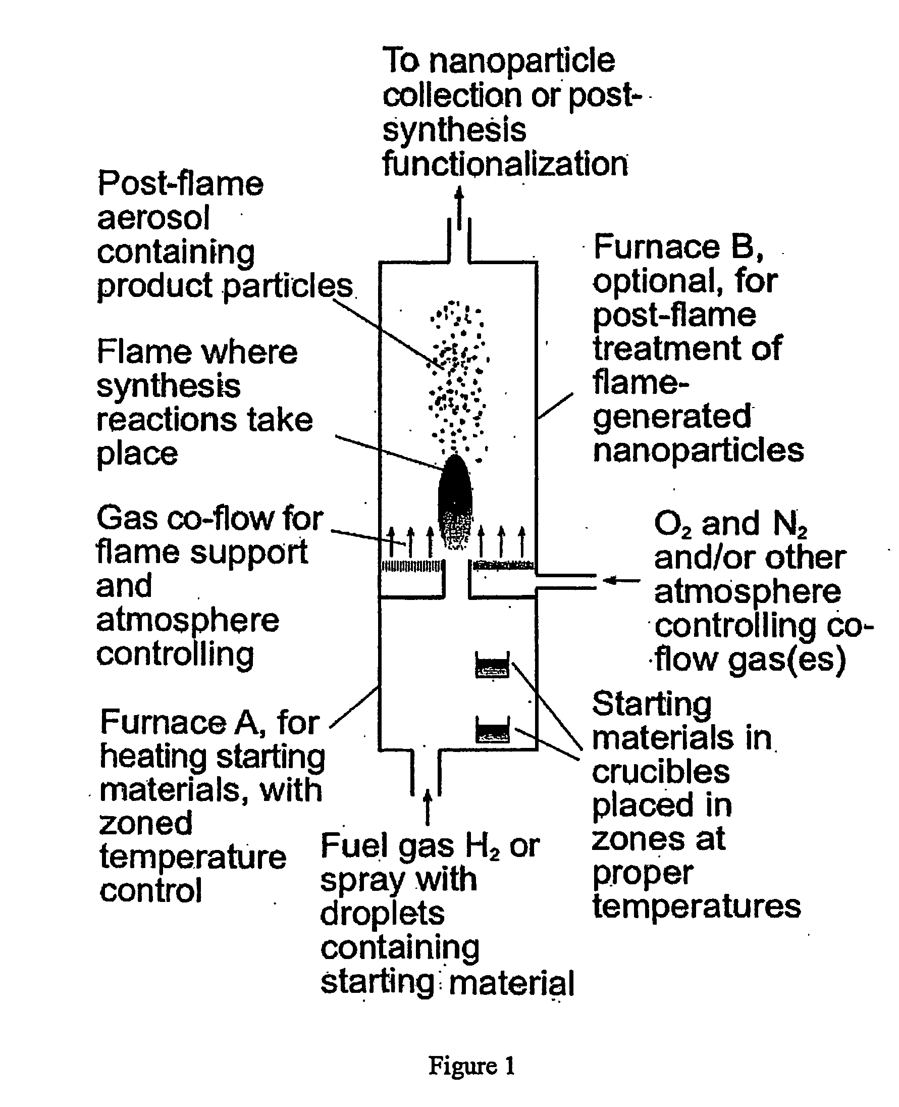
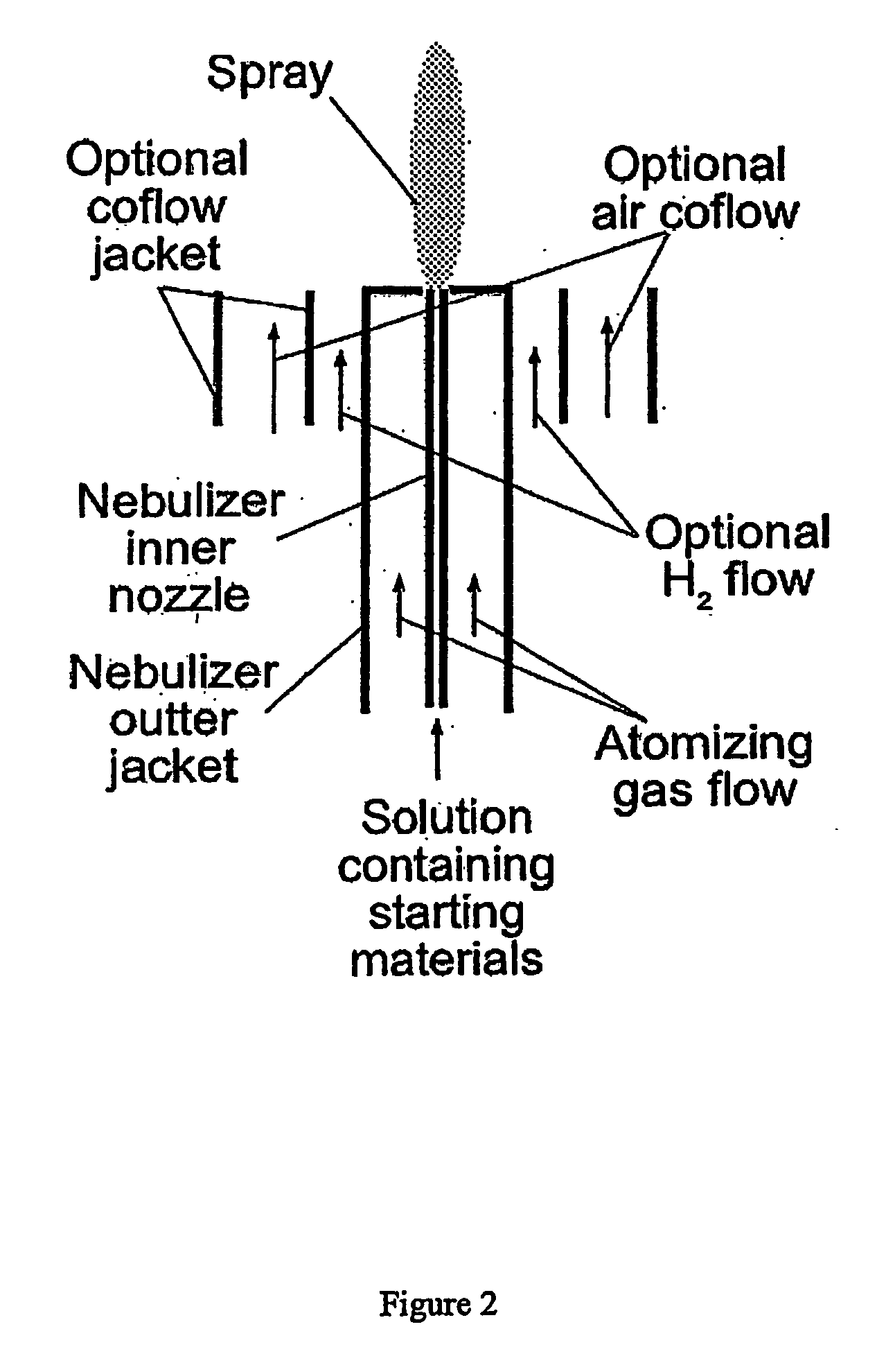
[0063] The synthesis conditions were the same as those described in Example 1, except sodium metal was not used. Pure O2 co-flow was used surrounding the outlet of furnace A, by mounting an optional co-flow jacket, as shown in FIG. 2. The flame temperature was about 2400° C. A transmission electron micrograph showing the size and morphology of the resulting nanoparticles is shown in the left panel of FIG. 6. A fluorescence emission spectrum of the resulting nanoparticles is shown in the right panel of FIG. 6. The excitation wavelength was 466 nm, fluorescence lifetime was on the order of 1 msec.


PUM

PropertyMeasurementUnit
diametersaaaaaaaaaa
diametersaaaaaaaaaa
diametersaaaaaaaaaa

Abstract

Fluorescent or phosphorescent nanoparticles, fluorescent or phosphorescent magnetic nanoparticles, combustion-based methods for their synthesis, and methods to functionalize them are described. The methods provided by the invention are simplified, efficient and cost effective as compared to prior art methods. The resulting fluorescent or phosphorescent nanoparticles have reduced tendency toward aggregation, and diminished need for postmanufacturing processing steps. The particles may be manufactured with combinations of lanthanides so as to absorb and emit light over a variety of wavelengths.

Description

CROSS REFERENCE TO RELATED APPLICATIONS [0001] This application claims the benefit of U.S. Provisional Patent Application Ser. No. 60 / 513,411, filed Oct. 22, 2003, the entire disclosure of which is incorporated herein by reference.STATEMENT REGARDING FEDERALLY SPONSORED RESEARCH OR DEVELOPMENT [0002] The U.S. Government has certain rights in this invention pursuant to Grant No. 5P42ES04699 awarded by the National Institutes of Health and Grant No. 0102662 awarded by the National Science Foundation.BACKGROUND OF THE INVENTION [0003] 1. Field of the Invention [0004] This invention relates to the fields of chemistry and biology. [0005] 2. Description of the Related Art [0006] Fluorescence is a widely used tool in chemistry and biological science. Fluorescent labeling of molecules is a standard technique in biology. The labels are often organic dyes that give rise to the usual problems of broad spectral features, short lifetime, photobleaching, and potential toxicity to cells. A further...

Claims


Application Information

Patent Timeline
Patent Type & Authority Applications(United States)
IPC IPC(8): B32B17/02B32B5/16C01F17/00C03B19/10C03C3/095C03C4/12C03C17/34C09K11/08G01NG01N21/64
CPCB82Y30/00C03B19/102C03C3/095C03C4/12C03C17/3405Y10T428/2996C09K11/7766C09K11/7783C09K11/7787G01N21/6428Y10T428/2998C09K11/7728
Inventor GUO, BINGKENNEDY, IAN M.DOSEV, DOSLMEINIKOV, DARINANICHKOVA, MIKAELA
Owner RGT UNIV OF CALIFORNIA
Why Eureka
Try Eureka