Magnetic material, and memory and sensor using same

a technology of magnetic materials and memory, applied in the field of magnetic materials, can solve the problems of not being able to immediately apply material to thermally assisted magnetic recording and magneto-optical recording, and the head cannot write to such recording media, so as to achieve high saturation magnetic flux density, reduce hc, and reduce the effect of coercive for

Active Publication Date: 2007-09-20
THE UNIV OF TOKYO +1
View PDF0 Cites 29 Cited by
  • Summary
  • Abstract
  • Description
  • Claims
  • Application Information

AI Technical Summary

Benefits of technology

[0038]For example, in a case in which In-containing ε-Fe2O3 is synthesized by a combination of the reverse micelle method and the sol-gel method, the copresence of an appropriate amount of an alkaline earth metal makes it easier to ultimately obtain the rod-shaped crystals. An alkaline earth metal (such as Ba, Sr, Ca, etc.) added as a shape control agent may remain in the In-containing ε-Fe2O3 crystal particles as an impurity. As well known there exist in polymorphisms such as α-Fe2O3 and γ-Fe2O3 which have the same composition as Fe2O3 but a different crystal structure, and exist also in another iron oxides such as FeO and Fe3O4. Those other iron oxide phases are permissible in the In-containing ε-Fe2O3 within an amount that does not prevent the effects of the invention. The silica coating formed on the surface of the iron hydroxide microparticles by the sol-gel method may also remain as an impurity in the In-containing ε-Fe2O3 crystal particles after the heat treatment. Depending on the application, the magnetic material used may be comprised of particles of the In-containing ε-Fe2O3 of the invention mixed with particles of ε-Fe2O3.
[0039]The preferred particle diameter along the long axis of the particles of In-containing ε-Fe2O3 of the invention, as measured from a transmission electron microscope (TEM) image, is from 5 to 200 nm, more preferably from 10 to 150 nm, and even more preferably from 10 to 100 nm. The particle diameter is the average particle diameter measured based on images of the particles observed using a TEM. The average diameter is obtained by magnifying a TEM image 600,000 times and measuring the largest diameter (the long-axis diameter, in the case of rod-shaped particles) of each of 100 isolated particles in the image. From the standpoint of applying the particles to a magnetic recording medium, it is desirable that the particles be fine particles each having a single domain structure in which the particle diameter in the TEM image is not more than 100 nm.
[0040]The magnetic material of this invention has such a huge coercive force at room temperature that if it was used as a magnetic powder to form the magnetic layer of a coating type magnetic recording medium, with the present state of the technology, it would be impossible to obtain, on the market, a magnetic head made of a material having a high enough saturation magnetic flux density to use with the recording medium. However, once a magnetic head is developed that can be used with the magnetic material of the invention, it will be possible to apply the material to coating type magnetic recording media. The In-containing ε-Fe2O3 particles of this invention can be used to form the magnetic layer of a magnetic recording medium by affixing powder particles having a particle diameter of from 5 to 200 nm, as measured along the long axis of the particles from a TEM image, to a substrate, with the easy magnetization axis of the particles at each site oriented in a prescribed direction. That is, the magnetic layer of a magnetic recording medium suitable for high-density recording is obtained by affixing particles of a powder composed of ε-InxFe2-xO3 (0<x≦0.30) in which In is substituted for a portion of the Fe sites of the ε-Fe2O3 crystal that exhibits an X-ray diffraction pattern similar to that of an ε-Fe2O3 crystal structure, having the same space group as that of an ε-Fe2O3, to a substrate with the easy magnetization axis of each particle crystal oriented in a prescribed direction.
[0041]On the other hand, in order to obtain a magnetic layer suitable for thermally-assisted magnetic recording or next-generation magneto-optical recording, it is essential that the magnetic material of the layer have the proper magnetic phase transition temperature and spin reorientation temperature. To reiterate what has already been stated with respect to the application of the material of the present invention, the concept of thermally-assisted magnetic recording is that data is recorded on a medium having a high Hc by using a laser to heat the medium to thereby lower the Hc enough to write the data; at room temperature the data, once written, is stably maintained. Thermally-assisted magnetic recording is regarded as the ultrahigh-density magnetic recording technology of the future. In the case of a magneto-optical disc, a laser is used to heat up localized areas of the medium to lower the Hc and enable data to be magnetically written. Stored data is read by projecting a light beam onto the disc and utilizing differences in the polarization angle of the reflected beam due to the direction of magnetization. Thus, it is a magnetic recording system that utilizes the magneto-optical effect.
[0042]In both thermally-assisted magnetic recording and magneto-optical recording, the recording medium is repeatedly heated and cooled, so the magnetic material used has to be chemically stable with respect to oxidation corrosion, thermally stable with respect to crystal transformation and crystallization, and have an appropriate optical absorption coefficient, reflectivity and other such properties. Being an oxide, the magnetic material composed of ε-Fe2O3 or In-containing ε-Fe2O3 can fully meet such requirements. The material also meets requirements related to magnetic properties, having a high Hc and a controllable magnetic phase transition temperature, an Hc that drops steeply with the heating up, and a high temperature-dependency.
[0043]Particular problems, in the case of thermally-assisted magnetic recording applied to hard disks, are those of the head-disk interface and the heating up of the head.

Problems solved by technology

However, the very hugeness of the Hc means that existing magnetic heads are unable to write to such recording media, and it is also unclear whether the material can be immediately applied to thermally-assisted magnetic recording and magneto-optical recording.
(495 K), which poses a problem from the standpoint of the head-disk interface.

Method used


Image

  • Magnetic material, and memory and sensor using same
  • Magnetic material, and memory and sensor using same
  • Magnetic material, and memory and sensor using same

Examples


example 1

[0050]In this example, ε-In0.12Fe1.88O3 was synthesized.

Step 1

[0051]A micelle solution I and a micelle solution II are prepared.

[0052]Preparation of Micelle Solution I

[0053]6 ml of pure water, 18.3 ml of n-octane and 3.7 ml of 1-butanol were put into a Teflon™ flask, to which were added 0.00287 mol of iron (III) nitrate 9-hydrate, 0.000135 mol of indium (III) nitrate 3-hydrate and 0.0003 mol of barium nitrate, and the solution dissolved at room temperature while being vigorously stirred. A surfactant consisting of cetyl trimethyl ammonium bromide was added in an amount that brought the water / surfactant mol ratio to 30, and the solution stirred to dissolve it, thereby obtaining the micelle solution I. The charged composition had been intended to correspond to those shown as a formula of In0.09Fe1.91O3.

[0054]Preparation of Micelle Solution II

[0055]2 ml of a 25% solution of aqueous ammonia was stirred into 4 ml of pure water.

[0056]This was followed by the addition of 18.3 ml of n-octan...

example 2

[0066]In this example, ε-In0.18Fe1.82O3 was synthesized.

[0067]This was done by the same procedure as Example 1, except that in the preparation of the micelle solution I, the amount of iron (III) nitrate 9-hydrate added was changed from 0.00287 mol to 0.00273 mol, and the amount of indium (III) nitrate 3-hydrate added was changed from 0.000135 mol to 0.00037 mol. The charged composition had been intended to correspond to those shown as a formula of In0.18Fe1.82O3.

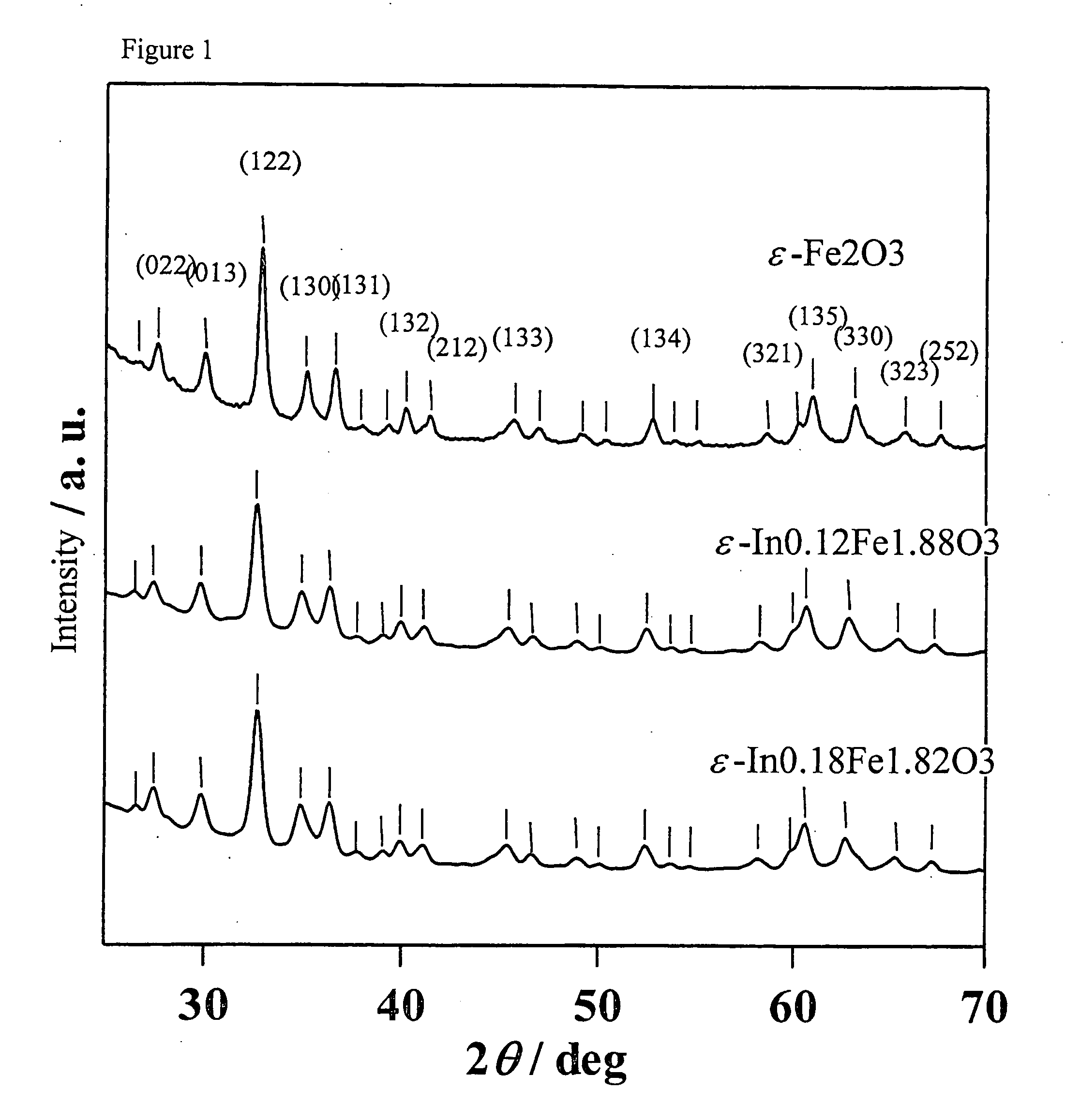
[0068]The sample thus obtained was measured by powder X-ray diffraction, resulting in the diffraction pattern shown at the bottom of FIG. 1. The peaks exhibited by this diffraction pattern correspond to those of the diffraction pattern of the ε-Fe2O3 crystal structure shown at the top of FIG. 1 (orthorhombic, space group Pna21). The calculated lattice constants of the sample were: a axis: 5.15 Å, b axis: 8.84 Å, c axis 9.53 Å.

[0069]Fluorescence X-ray analysis confirmed the composition of the sample to be ε-In0.18Fe1.82O3. Ro...

example 3

[0075]In this example, ε-In0.19Fe1.81O3 was synthesized.

[0076]This was done by the same procedure as Example 1, except that in the preparation of the micelle solution I, the amount of iron (III) nitrate 9-hydrate added was changed from 0.00287 mol to 0.002715 mol, and the amount of indium (III) nitrate 3-hydrate added was changed from 0.000135 mol to 0.000285 mol. The charged composition had been intended to correspond to those shown as a formula of In0.19Fe1.81O3.

[0077]The sample thus obtained was measured by powder X-ray diffraction, resulting in a diffraction pattern showing the sample to have a crystal structure similar to the ε-Fe2O3 of the Reference Example (orthorhombic, space group Pna21). Fluorescence X-ray analysis confirmed the composition of the sample to be ε-In0.19Fe1.81O3.

[0078]The cooling magnetization curve of the sample in a magnetic field was measured; the result is shown at the top of FIG. 5 (b) (just the portion up to 300 K). The spin reorientation temperature o...


PUM

PropertyMeasurementUnit
particle diameteraaaaaaaaaa
saturation magnetic flux densityaaaaaaaaaa
magnetic phase transition temperatureaaaaaaaaaa

Abstract

A magnetic material composed of ε-InxFe2-xO3 (wherein 0<x≦0.30) crystal in which In is substituted for a portion of the Fe sites of the ε-Fe2O3 crystal. The crystal exhibits an X-ray diffraction pattern similar to that of an ε-Fe2O3 crystal structure and has the same space group as that of an ε-Fe2O3. The In content imparts to the magnetic material a magnetic phase transition temperature that is lower than that of the ε-Fe2O3 and a spin reorientation temperature that is higher than that of the ε-Fe2O3. The In content can also give the magnetic material a peak temperature of the imaginary part of the complex dielectric constant that is higher than that of the ε-Fe2O3.

Description

FIELD OF THE INVENTION[0001]The present invention relates to an ε-Fe2O3 system magnetic material, and to a magnetic memory and temperature sensor using the magnetic material.DESCRIPTION OF THE PRIOR ART[0002]To increase the recording density of magnetic recording media, the magnetic particles concerned have to be made smaller and isolated. However, there is particular emphasis on maintaining a stable recording state as the size of the magnetic particles decreases. Specifically, the minimum unit of the magnetic energy (KU×V) of the cluster of magnetic particles constituting a recording bit has to be far larger than the thermal energy (kB×T) acting to disrupt the recording. Here, KU is the magnetic anisotropy energy constant, V is the volume of the magnetic cluster, kB is the Boltzmann constant, and T is absolute temperature (K). The ratio (KU×V) / (kB×T) is generally used as an index of the ability to stably maintain the recording state, with the aim being to achieve a ratio of about 6...

Claims


Application Information

Patent Timeline
Patent Type & Authority Applications(United States)
IPC IPC(8): G11B5/65B32B15/00
CPCB82Y25/00G11B5/70642G11B5/714Y10T428/11H01F1/0054Y10T428/115Y10T428/32H01F10/007
Inventor OHKOSHI, SHIN-ICHIHASHIMOTO, KAZUHITOSAKURAI, SHUNSUKEKUROKI, SHIRO
Owner THE UNIV OF TOKYO
Why Eureka
Try Eureka