Catalyst Material For Use In Fuel Cell, Catalyst Membrane, Membrane Electrode Assembly and Fuel Cell

Inactive Publication Date: 2007-10-04
FUJIFILM CORP
View PDF4 Cites 22 Cited by
  • Summary
  • Abstract
  • Description
  • Claims
  • Application Information

AI Technical Summary

Benefits of technology

[0009] The present invention has an aim of improving the utilization efficiency of catalyst particles, improving the permeability of a reaction gas near catalyst particles and preventing flooding of a catalyst membrane and it intends to p

Problems solved by technology

However, when the inventors have studied on those described in the examples of JP-A No. 2004-22346, it has been found that the sulfonic acid group introduced by the methods of preparation 1, 2 and 5 for the carbon material is instable to heat and involves a problem of dissociation with lapse of time and the sulfonic acid group introduced by the methods of preparation 3 and 5 for the carbon material involves a problem that the sul

Method used


Image

  • Catalyst Material For Use In Fuel Cell, Catalyst Membrane, Membrane Electrode Assembly and Fuel Cell
  • Catalyst Material For Use In Fuel Cell, Catalyst Membrane, Membrane Electrode Assembly and Fuel Cell
  • Catalyst Material For Use In Fuel Cell, Catalyst Membrane, Membrane Electrode Assembly and Fuel Cell

Examples


example 1

Manufacture of Catalyst Material for use in Fuel Cell (1)

[Manufacture of Catalyst Material for use in Fuel Cell M-1] (1-1 Type)

(Modification of Carbon Material)

[0375] As the carbon material, a carbon black (trade name of products: Carbon ECP, manufactured by Ketchen Black International Co.) (a) was used and reaction was conducted in accordance with the following scheme (1) (in the following scheme 1, CB shows a portion of the carbon black. CB has identical meaning here and hereinafter)

[0376] Reaction was conducted in accordance with the scheme (1). That is, 20 g of the carbon black (a), 180 mL of N,N-dimethyl formamide, 60 g of dibromopentane, and 24 g of potassium carbonate were added and reacted at 110° C. for 24 hours while stirring in a nitrogen gas stream. After the reaction, the product was washed with water and then with dichloromethane, and dried under a reduced pressure to obtain 19.9 g of a carbon material (c-1A), introduced with bromopentyl groups. As the result o...

example 2

Manufacture of Fuel Cell

[Manufacturing Method 1]

[0464] A fuel cell was manufactured by using the catalyst material for use in the fuel cell in Example 1. 2 g of each catalyst material for use in the fuel cell, 15 g of a Nafion solution as a binder (5% aqueous alcohol solution) were mixed and dispersed by a supersonic dispersing device for 30 min. The obtained dispersion was coated on carbon paper (350 μm thickness), dried and then punched into a circular shape of 9 mm diameter to manufacture a catalyst membrane.

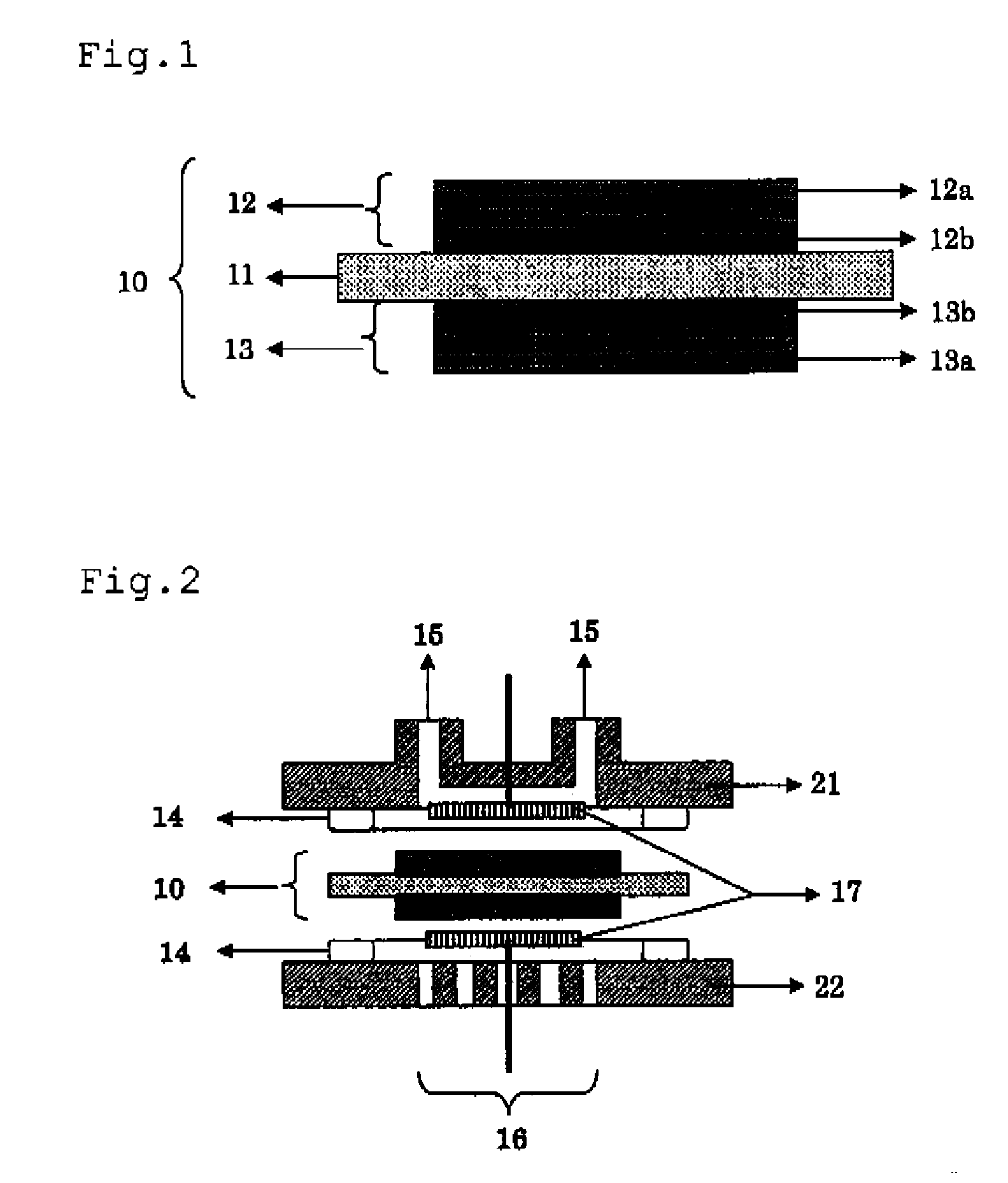
[0465] A Nafion 117 membrane was used as the solid electrolyte membrane and the catalyst membrane obtained as described above was bonded on both surfaces of the Nafion membrane 117 such that the coating surface was in contact with the Nafion membrane 117 and hot press bonded by hot press to manufacture an MEA.

[Manufacturing Method 2]

[0466] An MEA was manufactured in the same manner as in the preparation method 1 except for manufacturing the solid electrolyte and the bin...

example 3

Evaluation for Fuel Cell

[0467] The MEA obtained in Example 2 was set to a fuel cell shown in FIG. 2, and a hydrogen gas was caused to flow in anode side openings 15. In this case, an atmospheric air was caused to flow to cathode side openings 16. A potentiostat was connected between the anode electrode 12 and the cathode electrode 13 to record a current value at 400 mV. The result is shown in Table 1.

TABLE 1CatalystBinder - solidsupportingelectrolyteCurrent valuecarbonmembrane(A / cm2)RemarksM-1E-12.43InventionM-2E-12.26InventionM-3E-12.33InventionM-4E-12.53InventionM-5E-12.21InventionM-6Nafion 1172.19InventionM-7Nafion 1172.36InventionM-8E-12.28InventionM-9E-12.33InventionM-10Nafion 1172.21InventionM-11E-12.18InventionM-12E-12.46InventionM-13E-12.29InventionM-14Nafion 1172.11InventionM-15Nafion 1172.27InventionM-16Nafion 1172.01InventionM-17Nafion 1172.23InventionM-18Nafion 1172.23InventionM-19Nafion 1172.16InventionR-1Nafion 1171.68ComparativeExample[0468] It is recognized that ...


PUM


Abstract

A catalyst for a fuel cell comprising one or more hydrophilic segments and one or more hydrophobic segments jointly or separately connected to the surface of the carbon material by a single bond or a connection group having a solvolysis resistance and a heat resistance on a surface of a carbon material, wherein the hydrophilic segment has the solvolysis resistance and the heat resistance and has an ionic functional group, and the hydrophobic segment has the solvolysis resistance and the heat resistance and has no ionic functional group.

Description

BACKGROUND OF THE INVENTION [0001] 1. Field of the Invention [0002] The present invention concerns a fuel cell directly using, as a fuel, pure hydrogen, methanol, ethanol, dimethylether, methanol or reformed hydrogen from fossil fuels and using air or oxygen as an oxidizing agent and it particularly relates to a catalyst material, a membrane electrode assembly, and a fuel cell used in a solid polymer fuel cell. [0003] 2. Description of the Related Art [0004] A solid polymer fuel cell is a fuel cell having a feature in that an ion conductor, that is, an electrolyte is a solid and polymeric material, in which an ion exchange resin is used specifically as a solid polymer electrolyte, both negative electrode and positive electrode are disposed sandwiching the electrolyte therebetween, and electrochemical reaction is taken place by supplying, for example, hydrogen as a fuel to the negative electrode and oxygen or air to the positive electrode to generate electric power. [0005] That is, i...

Claims


Application Information

Patent Timeline
IPC IPC(8): H01M4/00H01M4/88H01M4/86H01M4/96H01M4/90
CPCH01B1/122H01M4/8663H01M4/9083Y02E60/50H01M4/926H01M2008/1095Y02E60/522H01M4/92
Inventor INASAKI, TAKESHINOMURA, KIMIATSU
Owner FUJIFILM CORP
Why Eureka
Try Eureka