Hollow Core Optical Ring Resonator Sensor, Sensing Methods, and Methods of Fabrication

a ring resonator and optical core technology, applied in the field of hollow core optical ring resonators, can solve the problems of degrading q-factors of micro-disks (or micro-rings), difficult mass production of microspheres, and limited use of evanescent wave sensors, etc., to achieve low sample consumption of ring resonators, high sensitivity, and high compatibility

Inactive Publication Date: 2007-10-11
UNIVERSITY OF MISSOURI
View PDF23 Cites 80 Cited by
  • Summary
  • Abstract
  • Description
  • Claims
  • Application Information

AI Technical Summary

Benefits of technology

[0012]The present invention provides a hollow core optical ring resonator (HCORR), which possesses the meritorious high sensitivity and low sample consumption of ring resonators, and at the same time, is highly compatible with well-developed capillary technologies for fluid delivery. As a result of its compatibility with liquid fluidics, the HCORR is alternatively referred to as an LCORR (i.e. liquid core optical ring resonator), although the HCORR is not limited to testing liquid samples. The inventive HCORR comprises a hollow optical tubing material with an outer diameter ranging from about 10 μm to about 1000 μm (preferably from about 30 μm to about 500 μm, more preferably from about 50 μm to about 300 μm) and

Problems solved by technology

In the past, evanescent wave sensors have generally been limited to fiber/waveguides, microspheres, and microdisks.
The relatively newer stand-alone microspheres and microdisks (or microrings) fabricated on a substrate were smaller and had greater sensitivity than the fiber/waveguides, but microspheres are difficult to mass-produce and micro-disks (or microrings) suffered from degraded Q-factors due to surface roughness created during the fabrication process.
Importantly, all of the evanescent wave sensors suffered from problems associated with efficiently combining fluidics and photonics, such that the two aspects did not interfere with one another (e.g. issues relating to effective fluid delivery, optical signal reliability, and high-throughput capability).
These problems were related to the fact that the evanescent field sensors of the past attempted to detect compositions located on the exterior of the sensor.
None of t

Method used


Image

  • Hollow Core Optical Ring Resonator Sensor, Sensing Methods, and Methods of Fabrication
  • Hollow Core Optical Ring Resonator Sensor, Sensing Methods, and Methods of Fabrication
  • Hollow Core Optical Ring Resonator Sensor, Sensing Methods, and Methods of Fabrication

Examples


example 1

[0091]The following example relates to a method of fabricating a HCORR. Specifically, an HCORR was formed by etching and pulling the center section of a fused silica capillary (r1˜0.45 mm, r2˜0.6 mm). The capillary was first pulled under an H2O flame (using the mechanical pulling set-up illustrated in FIG. 13) until the outer radius reaches about 35-50 μm. To achieve the desired wall thickness, the elongated capillary was etched by pumping low concentrations of HF (<10%), preferably about 5% HF, through the hollow care of the capillary for a period of 30 minutes to 2 hours. After final-etching, the resulting capillary was rinsed by pumping water through its hollow core, which yielded the desired HCORR with a wall thickness of about 2 to 4 μm. FIG. 17 shows an SEM image of about one quarter of the cross section of an HCORR.

example 2

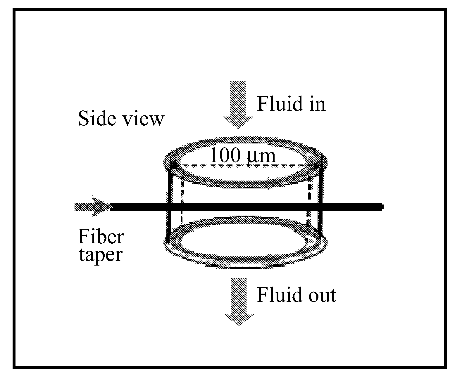
[0092]The HCORR device described in Example 1 was tested. During the sensing application, the HCORR was positioned in contact with a fiber taper of approximately 3-4 μm in diameter to obtain a WGM spectrum. Light from a tunable laser diode (980 nm) was coupled into the WGM through the evanescent coupling at the HCORR exterior surface. The tunable laser was repeatedly scanned across a wavelength range of about 100 μm. The WGM spectral positions were recorded at the output end of the taper.

[0093]The sensing capability of a HCORR sensor has been assessed by detecting changes in refractive index when a solution of ethanol and water was delivered through the sensor's hollow core. Incremental concentrations of 10%, 20%, 30%, 40%, 50%, and 60% were pumped through the HCORR with a rinsing step between each increment to ensure that the HCORR was free of residual ethanol from the prior increment. Two exemplary HCORRs were used with wall thickness of about 3.6 μm (▴ in FIG. 18) and 3.0 μm (▪ i...

example 3

[0096]In addition to the tests described above (ethanol and water), the HCORR device described in Example 1 was also tested on additional target analytes including methanol. In particular, the HCORR sensor has also been employed to detect changes in methanol concentration based on the changes in refractive index when a solution of methanol and water was delivered through the sensor's hollow core. Incremental concentrations of methanol (1%, 2%, 3%, 4%, 5%, 6%, 7%, 10%, 20% v / v in water) were pumped through the HCORR with an outer diameter of about 80 μm and a wall thickness of approximately 2 μm. A rinsing step between each increment was conducted to ensure that the HCORR was free of residual methanol from the prior increment. The result is shown in FIG. 19.

[0097]While the invention has been described in connection with specific embodiments thereof, it will be understood that the inventive method is capable of further modifications. This patent application is intended to cover any va...


PUM


Abstract

The present invention is directed to hollow core optical ring resonators (HCORRs), methods of fabricating HCORRs, and methods of using HCORRs in sensing applications. In particular, the evanescent field and whispering gallery modes of the HCORRs may be used to detect a target analyte within the hollow core of the HCORR. Other features of the present invention include utilizing the HCORR as part of a multiplex sensing device, including using the HCORR in capillary electrophoresis and chromatography applications.

Description

CROSS REFERENCE TO RELATED APPLICATIONS[0001]This application claims priority from U.S. Provisional Application Ser. No. 60 / 790,467 filed on Apr. 7, 2006, which is hereby incorporated by reference in its entirety. Additionally, all patents, published patent applications, and other references cited throughout this specification are hereby incorporated by reference in their entireties.FIELD OF THE INVENTION[0002]The present invention is directed generally to hollow core optical ring resonators (HCORRs), systems incorporating HCORRs, as well as methods of fabricating HCORRs. The present invention is also directed to methods of using HCORRs as whispering-gallery mode evanescent-wave sensors for small and large molecule detection, and for other sensing applications.BACKGROUND OF THE INVENTION[0003]In the past, evanescent wave sensors have generally been limited to fiber / waveguides, microspheres, and microdisks. The older fiber / waveguide sensors required large sample volumes. The relative...

Claims


Application Information

Patent Timeline
IPC IPC(8): G02B6/26
CPCG01N21/7746
Inventor FAN, XUDONGWHITE, IAN M.OVEYS, HESAM
Owner UNIVERSITY OF MISSOURI
Why Eureka
Try Eureka