Waste water and sludge treatment apparatus

a technology of sludge treatment and sludge, which is applied in the direction of water/sewage multi-stage treatment, other chemical processes, separation processes, etc., can solve the problems of deterioration of the flow of digested sludge, blockage of sludge pipes, and deterioration of the quality of treated water, etc., to achieve high map recovery rate, high purity, stable treatment

Active Publication Date: 2007-10-18
EBARA ENG SERVICE
View PDF1 Cites 41 Cited by
  • Summary
  • Abstract
  • Description
  • Claims
  • Application Information

AI Technical Summary

Benefits of technology

[0018] An object of the present invention is to solve the problems illustrated above by providing a treatment method and apparatus which satisfy aspects of both phosphorus removal and phosphorus recovery, enable the recovery of MAP having a high degree of purity, and enable stable treatment in which the MAP recovery rate is high and blockages of a liquid cyclone do not occur.

Problems solved by technology

When waste water containing such high concentrations of nitrogen and phosphorus is returned to a water treatment system, the nitrogen and phosphorus loads on the water treatment system increase, causing deterioration in the quality of the treated water.
However, when digested sludge or the separated liquid thereof is transported through pipes, so-called MAP precipitate is generated when the magnesium ions of the sludge chemically combine with the phosphate ions and ammonium ions, leading to possible blockages of the sludge pipe.
When the MAP precipitates into a draft tube in the digestion tank, the flow of the digested sludge deteriorates, and scale trouble such as pipe blockages during pump extraction occurs frequently.
However, this method focuses on phosphorus removal rather than the recovery of phosphorus resources, and hence there is demand for a treatment method which satisfies aspects of both phosphorus removal and phosphorus recovery.
Moreover, when MAP is recovered through aeration and centrifugal separation, the recovered matter contains digested sludge and screen residue as well as the MAP, and hence it is not always possible to recover MAP having a high degree of purity.
Furthermore, when MAP is recovered by subjecting the MAP to centrifugal separation using a liquid cyclone and the concentration of MAP or other inorganic solids introduced into the liquid cyclone is high, the liquid cyclone itself may become blocked.
In certain cases, the MAP concentration in an overflow riser may also increase, leading to deterioration in the recovery rate.
Further, when digested sludge containing MAP is transported by pipe to a facility for treating sludge collectively, a large amount of MAP scale is generated in the pipe, leading to deterioration in the efficiency with which the sludge is transported.
If MAP scale is left on the inside of the pipe, the entire sewer eventually becomes covered in MAP scale, making sludge transportation difficult, and hence cleaning and complicated maintenance must be performed periodically.
However, when sewage sludge is subjected to smelting treatment at a high temperature between 1200 and 1400° C., a part of the phosphorus contained in the sludge is emitted into the slag without solidifying, and as a result, the phosphorus becomes stuck during an exhaust gas treatment process, leading to problems such as machinery corrosion, an increase in the phosphorus load of the return water produced by exhaust gas wet cleaning, and so on.
As for crystallization reactors, when attempts have been made in the past to reduce the size of the crystallization reactor, the concentration ability of the liquid cyclone has posed a problem since it becomes difficult to maintain the MAP in the crystallization reactor at a high concentration.

Method used


Image

  • Waste water and sludge treatment apparatus
  • Waste water and sludge treatment apparatus
  • Waste water and sludge treatment apparatus

Examples


examples

[0261] The present invention will now be described more specifically and in further detail using examples.

Examples 1 to 3 and Comparative examples 1 and 2 correspond to the embodiment described above with reference to FIGS. 1 to 3.

example 1

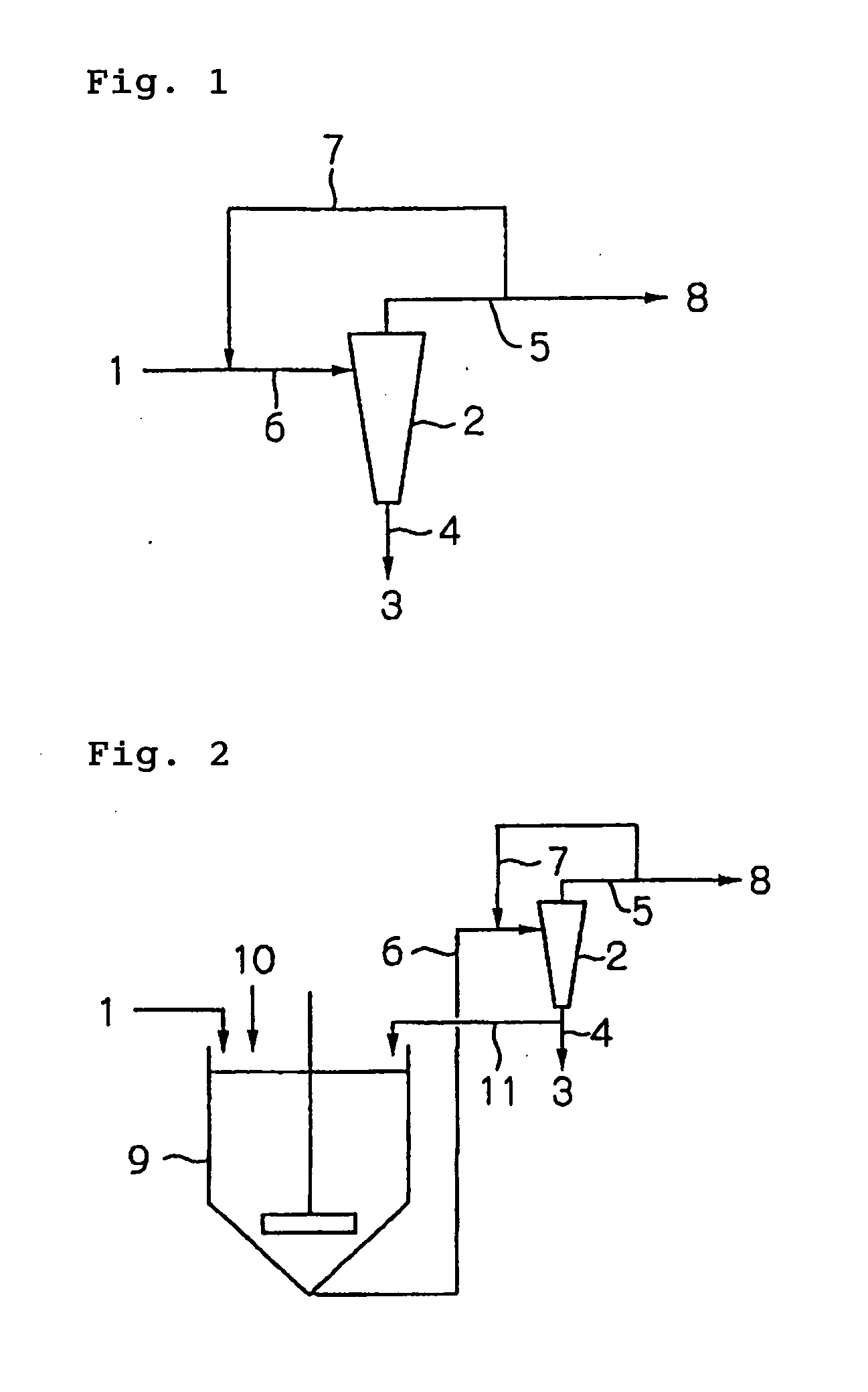
[0262] In this example, a performance test was performed on a liquid cyclone using raw sludge obtained by adding MAP prepared in advance to anaerobically digested sludge at 80 g / liter. The apparatus treatment flow is shown in FIG. 1.

[0263] A two-inch cyclone was used as the liquid cyclone 2. To increase the MAP concentration rate, the diameter of the sludge discharge pipe was set at 15 mm and the diameter of the micro-particle discharge pipe was set at 5 mm. The flow rate of the sludge introduced into the liquid cyclone 2 was set at 4 m3 / hr, and the introduction pressure was set at 0.45 Mpa. The supply rate of the raw sludge 1 was set at 0.6 m3 / hr, the circulation rate of the sludge treated by the liquid cyclone 2 (the amount circulated by the pipe 7) was set at 3.4 m3 / hr, and the circulation ratio (treated sludge circulation rate / raw sludge supply rate) was set at 5.7. The MAP concentration of the treated sludge 8 was 0.2 g / liter, as opposed to a MAP concentration of 80 g / liter in...

example 2

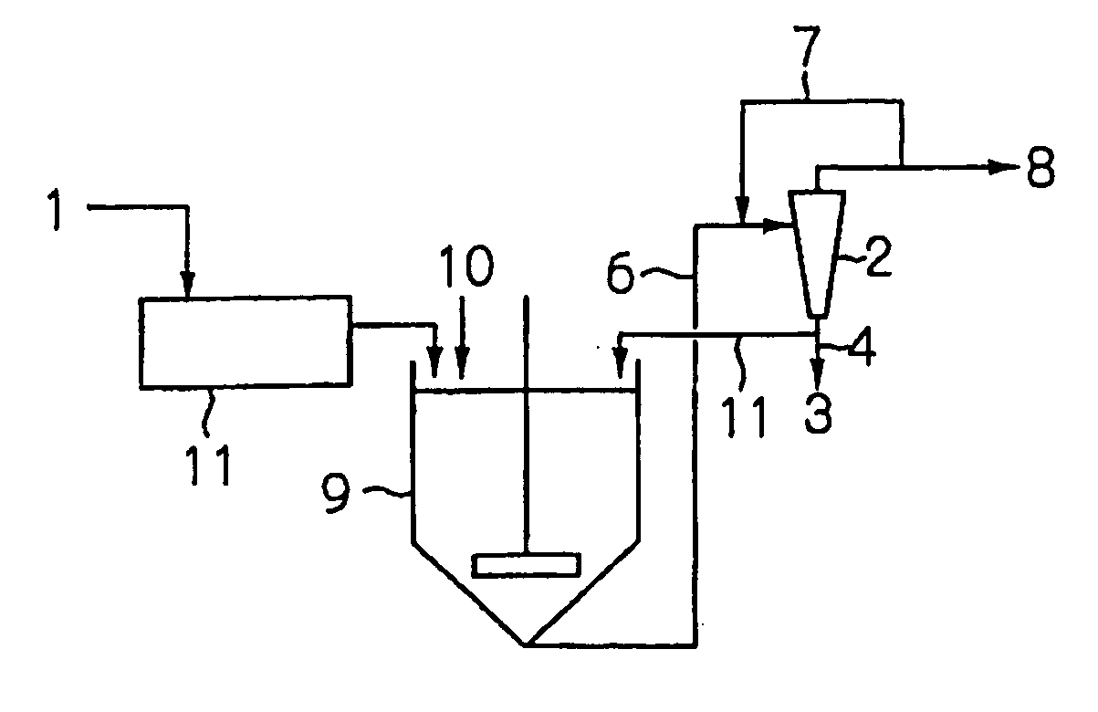
[0264] In this example, a phosphorus removal test was performed on digested sludge extracted from a digestion tank of a sewage treatment plant. The treatment flow is shown in FIG. 3.

[0265] The treatment flow was constituted by the sieve method screen residue removal apparatus 11, the crystallization reactor 9, and the liquid cyclone 2. The digested sludge 1 was treated by a vibrating screen having an aperture of 2.0 mm serving as the screen residue removal apparatus 11 to remove screen residue, and then introduced into the crystallization reactor 9. Magnesium chloride 10 was added to the crystallization reactor 9 to obtain an Mg / P molar ratio of 1 in relation to the orthophosphate ion concentration of the digested sludge, and a pH adjusting agent was added to adjust the pH to 8.0. The MAP concentration in the crystallization reactor 9 was maintained at 40 g / liter. Sludge obtained by mixing together a part of the sludge 6 in the crystallization reactor 9 and a part 7 of the treated ...


PUM

PropertyMeasurementUnit
temperatureaaaaaaaaaa
specific gravityaaaaaaaaaa

Abstract

In a system for separating crystals from sludge, or from separated water generated when sludge is subjected to a concentration process or a dewatering process, aspects of both phosphorus removal and phosphorus recovery can be satisfied, MAP having a high degree of purity can be recovered, and stable treatment can be performed such that the MAP recovery rate is high and blockages of a liquid cyclone do not occur. An aspect of the present invention is a crystal separation apparatus for separating crystals from sludge, or from separated water generated when sludge is subjected to a concentration process or a dewatering process, comprising a liquid cyclone for separating the crystals from the sludge or separated water introduced into the liquid cyclone, and a return pipe A for returning the sludge or separated water which flows out from an overflow riser of the liquid cyclone to a sludge or separated water introduction portion of the liquid cyclone.

Description

BACKGROUND OF THE INVENTION [0001] 1. Field of the Invention [0002] The present invention relates to an apparatus and method for separating and concentrating crystals from anaerobic or aerobic sludge, separated water generated when sludge is subjected to a concentration process or dewatering process, or various kinds of waste water. The present invention also relates to an apparatus and method for treating digested sludge generated when organic waste matter or waste water is subjected to anaerobic digestion. [0003] 2. Description of the Related Art [0004] In a treatment facility for treating organic waste water containing phosphorus and nitrogen, such as sewage, waste water, and screen, first the raw sludge (also referred to as preliminary sludge hereafter) is subjected to liquid / solid separation in a preliminary sedimentation tank, whereupon the separated supernatant liquid is subjected to activated sludge treatment to remove organic matter. During the activated sludge treatment, t...

Claims


Application Information

Patent Timeline
Patent Type & Authority Applications(United States)
IPC IPC(8): C02F11/04C02F11/14C02F3/28C02F1/52C02F11/127C02F11/143
CPCC02F11/127C02F11/14C02F2209/06C02F2101/105C02F2001/5218C02F11/143
Inventor SHIMAMURA, KAZUAKIHAGINO, TAKAOISHIKAWA, HIDEYUKIFUCHU, YUICHI
Owner EBARA ENG SERVICE
Why Eureka
Try Eureka