Conducting ceramics for electrochemical systems

a technology of electrochemical systems and conductors, applied in the direction of electrode manufacturing processes, liquid-gas reaction processes, combustible gas production, etc., can solve the problems of advanced hydrogen gas separation methods, energy-intensive pressure swing adsorption techniques,

Inactive Publication Date: 2007-10-25
ACUMENTRICS
View PDF25 Cites 5 Cited by
  • Summary
  • Abstract
  • Description
  • Claims
  • Application Information

AI Technical Summary

Benefits of technology

[0011] In some embodiments, the second portion involves a mixed ionically and electrically conducting material which physically isolates the water produced in the first portion from a second fuel provided in the second portion, except for ionic and / or electronic conduction across the mixed conducting material. In this way, the second fuel, including any impurities if present, can be physically isolated from the first portion, thereby preventing contamination of the first portion if such contamination could be detrimental to the first portion.

Problems solved by technology

However, pressure swing adsorption techniques can be energy intensive and cannot be performed in a continuous manner.
However, fouling of these materials, as well as cost and energy intensity, are among the reasons that more advanced hydrogen gas separation methods are still needed.

Method used


Image

  • Conducting ceramics for electrochemical systems
  • Conducting ceramics for electrochemical systems
  • Conducting ceramics for electrochemical systems

Examples


example 1

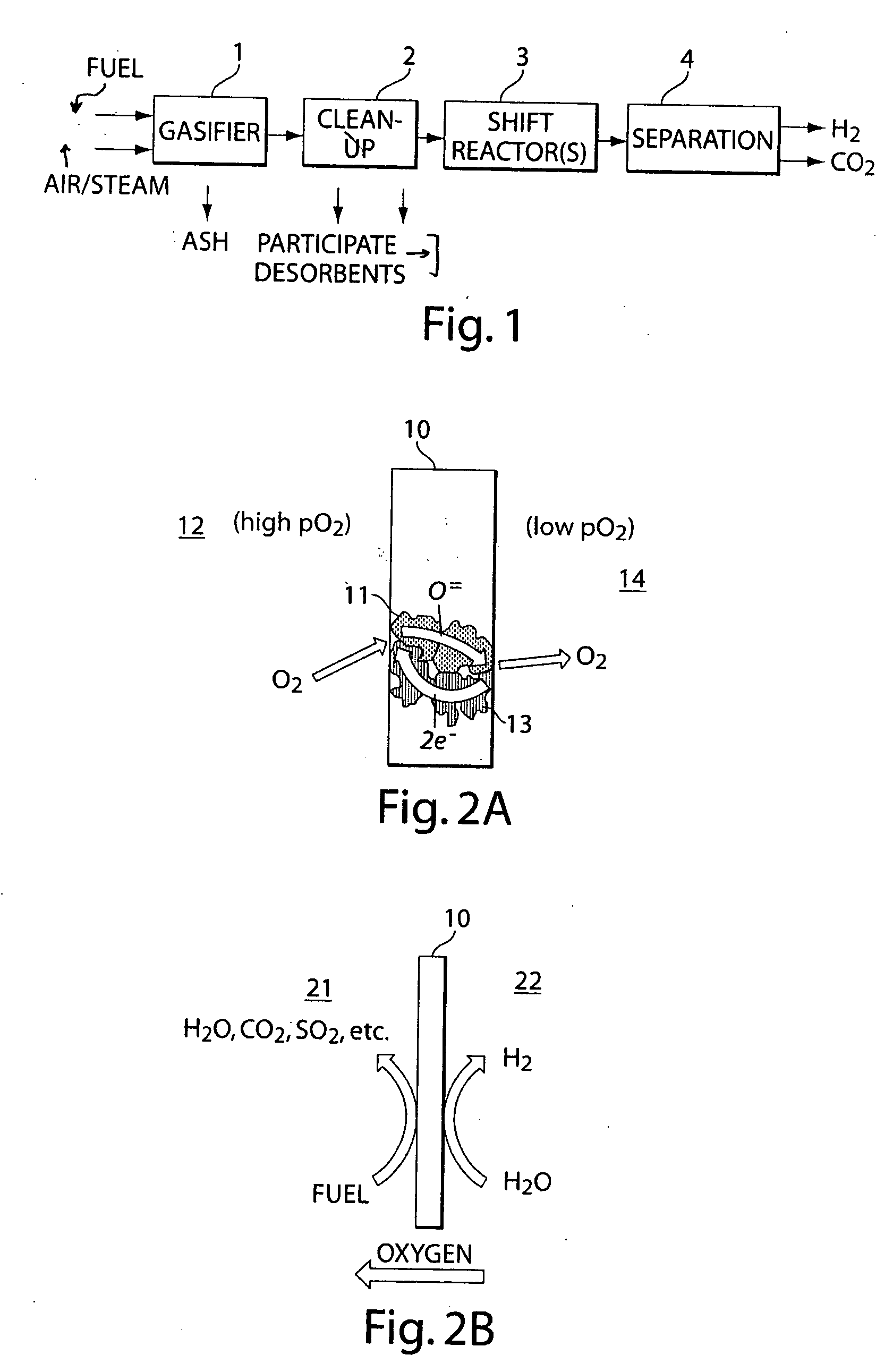
[0083] In this example, the hydrogen yield from a ceramic that is used to separate an oxidizable species on one side and a reducible species on the other side (see FIG. 2), is calculated. The ceramic is short circuited by the electron flow.

[0084] In such cases, an electrical current, I, according to Ohm's law, may be expected: I=VR.

[0085] The voltage V can be calculated from the ratio of partial oxygen pressures on either side of the membrane using the Nernst equation. The resistance, R, can be divided into at least the following components: (1) a polarization resistance on the cathode due to the charge transfer, Rc; (2) an ohmic resistance resulting from the ionic transport through the membrane, Ri; (3) a polarization resistance on the anode due to the charge transfer, Ra; and (4) an electronic resistance that short circuits the cell, Re:

R=Rc+Ri+Ra+Re

The electronic resistance, Re, can be made negligible relative to R, in some embodiments, by an appropriate choice of ionic and / ...

example 2

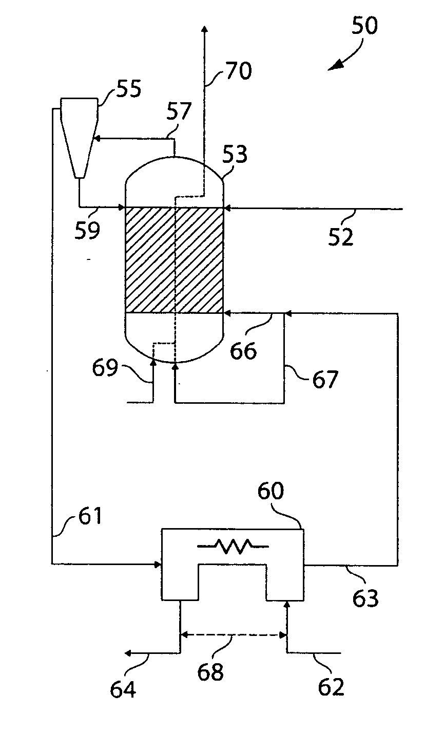
[0088] This example illustrates a reactor according to one embodiment of the invention. The reactor used in this example is schematically shown in FIG. 4. Table 2 shows the mass and energy balances for a 1 MW hydrogen production system. The difference in enthalpy flows between the H2 line 64 and the steam line 62 in Table 3 is the latent heat value (1 MW) of the produced hydrogen. It has been assumed in this example that in steam line 62 in the table a fraction of hydrogen is present. In a complete system this may be derived from the product stream. In stream a the ratio of CO to CO2 is set equal to 8. This is the equilibrium value that would be obtained in a gasifier operating at 800° C. in the presence of C, CO, and CO2.

[0089] Going from stream 57 to stream 63, the gas passes through the separator and the magnitude of the CO flow reduces as much as the CO2 flow increases. The formation of CO2 might seem rather low in relation to the total flow that enters the separator. This, how...

example 3

[0094] The following example illustrates the production of a mixed ionically and electrically conducting ceramic for use in a reactor, according to one embodiment of the invention.

[0095] Initially, a support tube was extruded and dried. The support tube is formed from Ni-YSZ, although the extrusion dough may contain, besides the Ni-YSZ precursors, binders, pore-formers etc. The Ni-YSZ tube was extruded using standard extrusion techniques known to those of ordinary skill in the art. The tube had a wall thickness of 1 mm and a diameter (green) of 9 mm. The tube was allowed to dry and harden before next step.

[0096] Next, a caps were added to the tube. The caps were circles cut from a green Ni-YZY sheet, and glued onto ends of tubes to form caps using Ni-YSZ slurry in a solvent. The cap was then bisque fired in air for 2 hours at 1100° C. An inner functional layer was then applied, after the tube had cooled. The functional layer was prepared by dip-coating the ceramic in a solution co...


PUM

PropertyMeasurementUnit
thicknessaaaaaaaaaa
resistivityaaaaaaaaaa
pressureaaaaaaaaaa

Abstract

The present invention generally relates to conducting materials such as mixed ionically and electrically conducting materials. A variety of materials, material compositions, materials with advantageous ratios of ionically and electrically conducting components, structures including such materials, and the like are provided in accordance with the invention. In one aspect, the invention relates to conducting ceramics for electrochemical systems and, in particular, to mixed ionically and electrically conducting ceramics which can be used, for example, for electrochemical systems and, in particular, to mixed ionically and electrically conducting ceramics which can be used, for example, for hydrogen gas generation from a gasified hydrocarbon stream. One aspect of the invention provides a material comprising a first phase comprising a ceramic ionic conductor, and a second phase comprising a ceramic electrical conductor. An example of such a material is a material comprising ZrO2 doped with Sc2O3 and SrTiO3 doped with Y2O3. Another aspect of the invention provides systems and methods of hydrogen gas generation from a fuel, such as a carbonaceous fuel, using materials such as those described above, for example, present within a membrane in a reactor. In some embodiments, a substantially pure hydrogen stream may be generated through in situ electrolysis. In some cases, a material such as those described above may be used to facilitate ion and / or electron exchange between a first reaction involving a fuel such as a carbonaceous fuel, and a second reaction involving a water-hydrogen conversion reaction (i.e., where water is reduced to produce hydrogen gas). In other aspects, the invention provides systems and methods for producing power from a fuel source, such as a carbonaceous fuel source.

Description

RELATED APPLICATIONS [0001] This application is a continuation of International Patent Application Serial No. PCT / US2005 / 035714, filed Oct. 5, 2005, entitled “Conducting Ceramics for Electrochemical Systems,” by Rackey, et al., which claims priority to U.S. Provisional Patent Application Ser. No. 60 / 616,475, filed Oct. 5, 2004, entitled “Conducting Ceramics for Hydrogen Generation,” by Rackey, et al.; and of U.S. Provisional Patent Application Ser. No. 60 / 662,321, filed Mar. 16, 2005, entitled “Conducting Ceramics for Electrochemical Systems,” by Rackey, et al. Each of the above applications is incorporated herein by reference.FIELD OF INVENTION [0002] The present invention generally relates to conducting ceramics for electrochemical systems and, in particular, to mixed ionically and electrically conducting ceramics. BACKGROUND [0003] Currently, there is great interest in using hydrogen as a fuel source. Hydrogen can be produced, for example, from carbonaceous fuels. Conventional me...

Claims


Application Information

Patent Timeline
Patent Type & Authority Applications(United States)
IPC IPC(8): B01J10/00
CPCB01D69/141Y02E60/526B01D2325/14B01J12/007B01J19/2475B01J2219/00103C01B3/042C01B3/36C01B3/38C01B3/501C01B13/0207C01B13/0251C01B2203/0405C01B2203/066C01B2203/84C01B2210/0046C01B2210/0053C04B35/01C04B35/2641C04B35/47C04B35/486C04B35/488C04B35/4885C04B2235/3206C04B2235/3208C04B2235/3213C04B2235/3215C04B2235/3224C04B2235/3225C04B2235/3227C04B2235/3232C04B2235/3236C04B2235/3241C04B2235/3246C04B2235/3262C04B2235/3272C04B2235/3275C04B2235/3279C04B2235/3281C04B2235/3284C04B2235/3286C04B2235/80C04B2235/96C10J3/00C10J2300/1618H01M4/0433H01M8/0612H01M8/0618H01M8/0631H01M8/0643H01M8/0656H01M8/083H01M16/00H01M2008/1095H01M2008/147Y02E60/364Y02E60/366Y02E60/50B01D71/024Y02E60/36Y02E60/10H01M8/04H01M8/06C01B3/34B01D71/0271
Inventor BOERSMA, REINDER J.WANG, GONGHOURACKEY, SCOTT C.
Owner ACUMENTRICS
Why Eureka
Try Eureka