Display device, driving method of display device, and electronic appliance

a display device and driving method technology, applied in semiconductor devices, instruments, computing, etc., can solve the problems of insufficient suppression of image quality degradation, and achieve the effects of improving display quality, clear image, and reducing pseudo contour

Inactive Publication Date: 2007-12-06
SEMICON ENERGY LAB CO LTD
View PDF28 Cites 47 Cited by
  • Summary
  • Abstract
  • Description
  • Claims
  • Application Information

AI Technical Summary

Benefits of technology

[0041]In the invention, by combination of an area gray scale method and a time gray scale method, multiple gray scale display can be performed and a pseudo contour can be reduced. Accordingly, display quality can be improved and a clear image can be obtained. Further, a duty ratio (a ratio of a lighting period in one frame) can be improved as compared with a conventional time gray scale method, and luminance can be improved. By improvement in the duty ratio, a voltage applied to a light emitting element can be reduced. Therefore, power consumption can be reduced and deterioration of the light emitting element can be suppressed.

Problems solved by technology

As described above, it is difficult to realize high-definition and multiple gray scales only by the conventional area gray scale method; and a pseudo contour occurs only by the conventional time gray scale method, so that deterioration of image quality cannot be sufficiently suppressed.

Method used


Image

  • Display device, driving method of display device, and electronic appliance
  • Display device, driving method of display device, and electronic appliance
  • Display device, driving method of display device, and electronic appliance

Examples


embodiment mode 1

[0124]In this embodiment mode, an example where a driving method of the invention is applied to a case of 6-bit display (64 gray scales) is described.

[0125]A driving method according to this embodiment mode is a driving method using a combination of an area gray scale method in which one pixel is divided into a plurality of subpixels and a gray scale is expressed by control of the number or the area of lighting subpixels; and a time gray scale method in which one frame is divided into a plurality of subframes, each subframe is weighted with respect to the frequency of light emission, a light emitting period, or the like, and then the total weight is differentiated for each gray scale level, thereby expressing a gray scale. That is, one pixel is divided into m subpixels (m is an integer of m≧2). In the m subpixels, the area of the (s+1)th subpixel (1≦s≦m−1) is twice the area of the s-th subpixel, in other words, a ratio of the area of the s-th subpixel to the area of the (s+1)th subp...

embodiment mode 2

[0230]In Embodiment Mode 1, a case where a lighting period increases in linear proportion to the increase of a gray scale level is described. In this embodiment mode, a case where gamma correction is performed is described.

[0231]Gamma correction is referred to a method by which a lighting period increases nonlinearly as a gray scale level increases. Human eyes cannot sense that luminance increases in proportion even when luminance increases in linear proportion. As luminance increases, difference of brightness is less visible to human eyes. Therefore, in order to sense the difference of brightness by human eyes, it is necessary to increase a lighting period as a gray scale level increases, that is, gamma correction is necessary to be performed. When a gray scale level is represented by x and luminance is represented by y, a relation between the luminance and the gray scale level is expressed by Formula 1.

[Formula 1]y=Axγ  (1)

[0232]Note that in Formula 1, A is a constant for normaliz...

embodiment mode 3

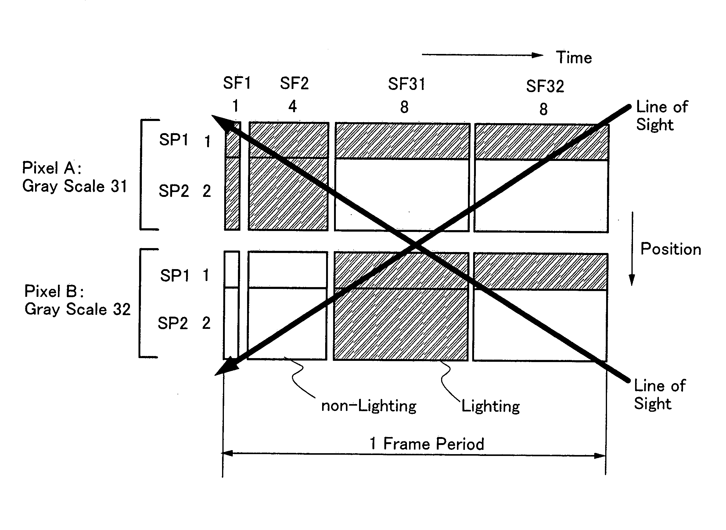
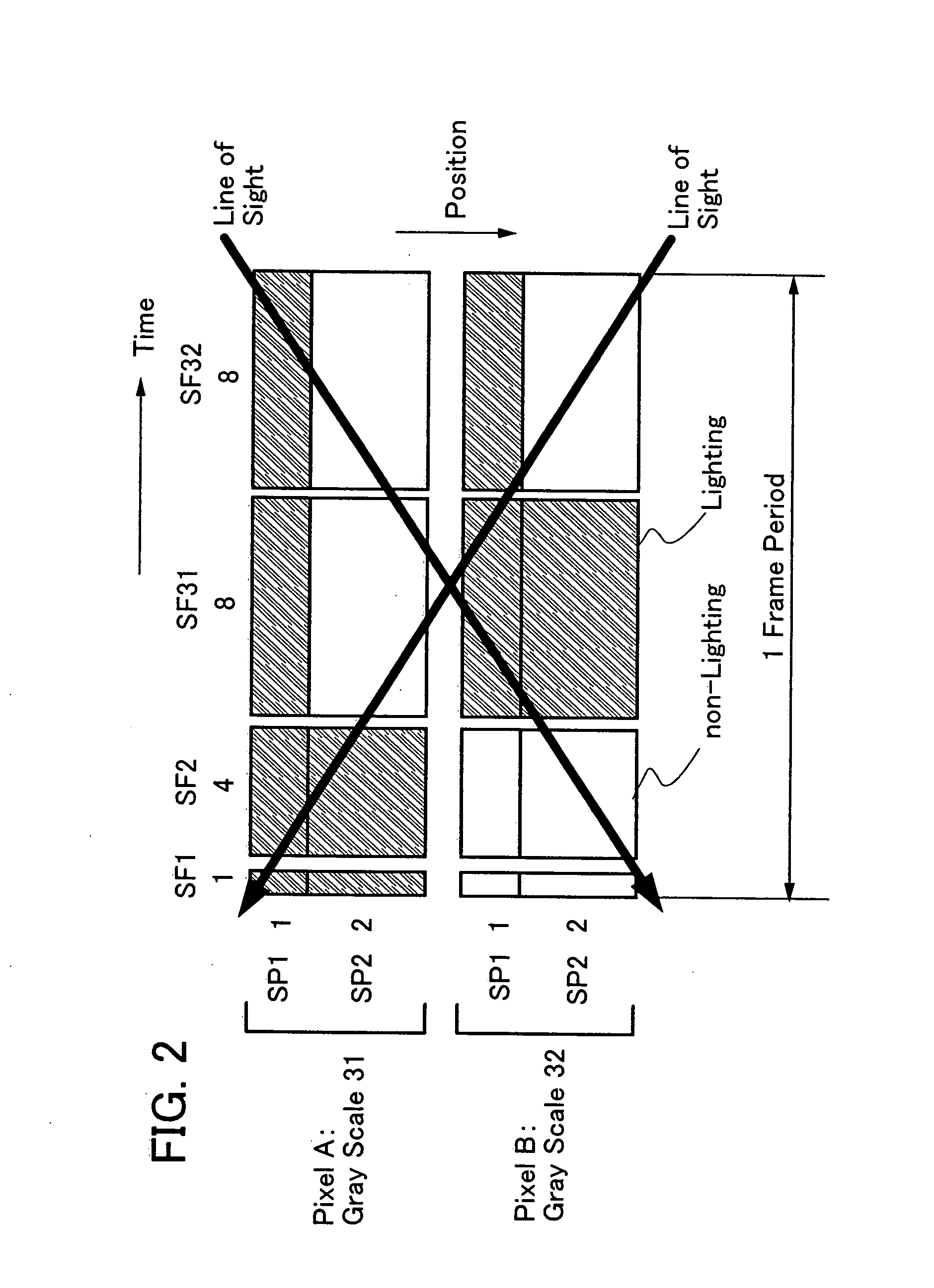
[0245]In Embodiment Mode 1, the overlapping time gray scale method is applied to subframes of which light emission intensity is the same in each subpixel; however, the invention is not limited thereto. In this embodiment mode, a case is described, in which the overlapping time gray scale method is applied to all subframes in each subpixel.

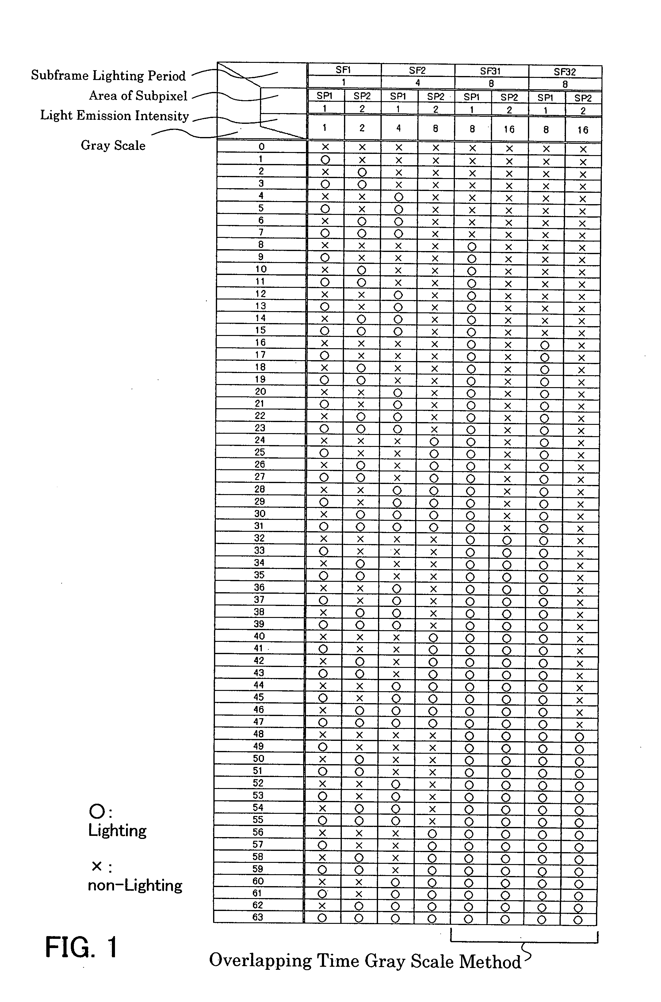
[0246]In this embodiment mode, a case is described, in which one pixel is divided into two subpixels (SP1 and SP2) each having the same area; and one frame is divided into eight subframes (SF1 to SF8) each having the same lighting period. FIG. 32 shows a selection method of a subpixel and a subframe in this case.

[0247]Here, the subpixels have the following areas: SP1=SP2=1, and the subframes have the following lighting periods: SF1=SF2=SF3=SF4=SF5=SF6=SF7=SF8=1.

[0248]In FIG. 32, since the area of each subpixel is the same and the lighting period of each subframe is the same, light emission intensity is equal in all the subpixels and in all the subf...


PUM


Abstract

An object is to reduce a pseudo contour occurring in time gray scale method display. One pixel is divided into m subpixels (m is an integer of m≧2), and the area of the (s+1)th subpixel (1≦s≦m−1) is twice the area of the s-th subpixel. Further, one frame is divided into n subframes (n is an integer of n≧2), and a lighting period of the (p+1)th subframe (1≦p≦n−1) is 2m times longer than a lighting period of a p-th subframe. Then, at least one subframe of the n subframes is divided into a plurality of subpixels each having a lighting period shorter than that of the subframe so that the n subframes are increased to t subframes (t>n). In at least one subframe of the t subframes, lighting periods of the subframes in a lighting state are sequentially added by the m subpixels, so that a gray scale of the pixel is expressed. (174 words)

Description

BACKGROUND OF THE INVENTION[0001]1. Field of the Invention[0002]The present invention relates to a display device and a driving method thereof, particularly relates to a display device to which an area gray scale method is applied and a driving method thereof.[0003]2. Description of the Related Art[0004]In recent years, a so-called self-light emitting display device of which pixel is formed using a light emitting element such as a light emitting diode (LED) has attracted attention. As a light emitting element used for such a self-light emitting display device, an organic light emitting diode (also referred to as an OLED (Organic Light Emitting Diode), an organic EL element, an electroluminescence (EL) element, or the like) has attracted attention, and has been used for an EL display and the like. Since a light emitting element such as an OLED is a self-light emitting type, it has advantages of high visibility of pixels, no backlight required, high response speed, and the like over a...

Claims


Application Information

Patent Timeline
Patent Type & Authority Applications(United States)
IPC IPC(8): G09G3/30G09G3/288
CPCG09G3/2022H01L27/1225G09G3/288G09G3/3233G09G2300/0443G09G2300/0452G09G2300/0465G09G2300/0842G09G2300/0861G09G2300/0866G09G2310/0262G09G2320/0261G09G2320/0266G09G2330/021G09G3/2074G09G3/20G09G3/296G09G3/30G09G3/32
Inventor KIMURA, HAJIMESHISHIDO, HIDEAKIYAMAZAKI, SHUNPEI
Owner SEMICON ENERGY LAB CO LTD
Why Eureka
Try Eureka