Ultrasonic energy system and method including a ceramic horn

a technology of ultrasonic energy system and ceramic horn, which is applied in the field of ultrasonic energy system and method incorporating ceramic horn, can solve the problems of molten aluminum, unacceptable accepted horn materials, and inability to provide acceptable, etc., and achieves the effects of facilitating long-term operation, high corrosion and molten aluminum

Inactive Publication Date: 2007-12-20
3M INNOVATIVE PROPERTIES CO
View PDF24 Cites 2 Cited by
  • Summary
  • Abstract
  • Description
  • Claims
  • Application Information

AI Technical Summary

Benefits of technology

[0009] One aspect of the present invention relates to an acoustic system for applying vibratory energy, including a horn connected to an ultrasonic energy source. At least a leading section of the horn is comprised of a ceramic material. More particularly, the horn defines an overall length and wavelength. The ceramic material leading section has a length of at least ⅛ the horn wavelength. In one embodiment, an entirety of the horn is a ceramic material, and is mounted to a separate component, such as a waveguide, via an interference fit. Regardless, by utilizing a ceramic material for at least a leading section of the horn, the ultrasonic system of the present invention facilitates long-term operation in extreme environments such as high temperature and / or corrosive fluid mediums. For example, it has surprisingly been found that ceramic-based horns such as SiN4, sialon, Al2O3, SiC, TiB2, etc., have virtually no chemical reactivity when applying vibratory energy to highly corrosive and molten metal media, especially molten aluminum.

Problems solved by technology

However, the waveguide is not a required component and is not always employed.
However, with certain other ultrasonic applications, wear concerns may arise.
In particular, where the horn operates in an intense environment (e.g., corrosive and / or high temperature), accepted horn materials may not provide acceptable results.
The molten aluminum represents an extremely harsh environment, as it is both intensely hot (on the order of 700° C.) and chemically corrosive.
Under severe conditions, titanium and steel horns will quickly deteriorate.
Even with this more rigorous material selection, niobium-based horns provide a limited working life in molten aluminum before re-machining is required.
Moreover, near the end of their “first” life, niobium alloy horns become unstable, potentially creating unexpected processing problems.
In addition, formation of the niobium-molybdenum alloy horns entails precise, lengthy and expensive casting, hot working, and final machining operations.
In view of the high cost of these and other materials, niobium (and its alloys) and other accepted horn materials are less than optimal for harsh environment ultrasonic applications.
For certain implementations, however, the intense environment in which the ultrasonic horn operates renders current horn materials economically unavailing.

Method used


Image

  • Ultrasonic energy system and method including a ceramic horn
  • Ultrasonic energy system and method including a ceramic horn
  • Ultrasonic energy system and method including a ceramic horn

Examples


example 1

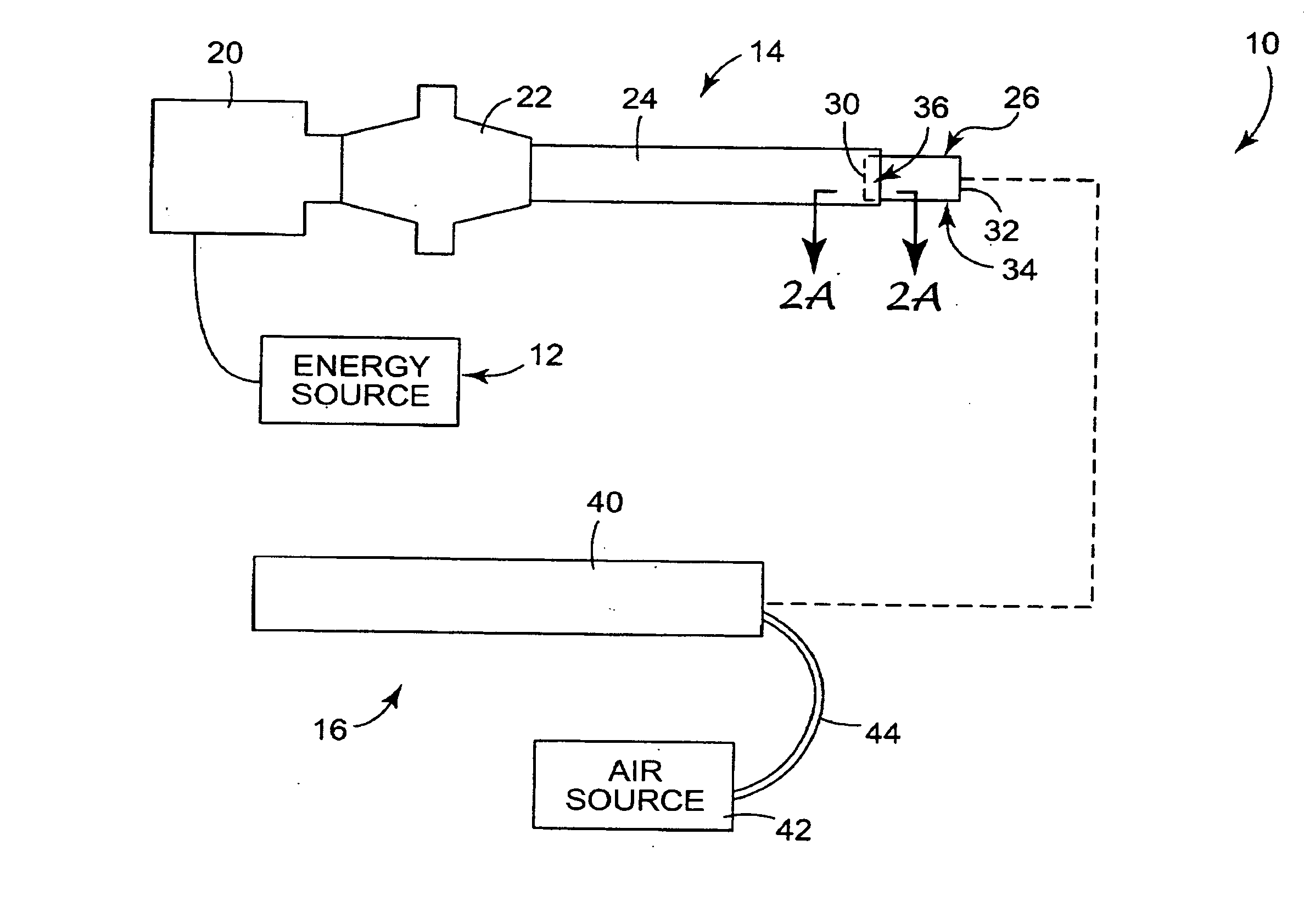
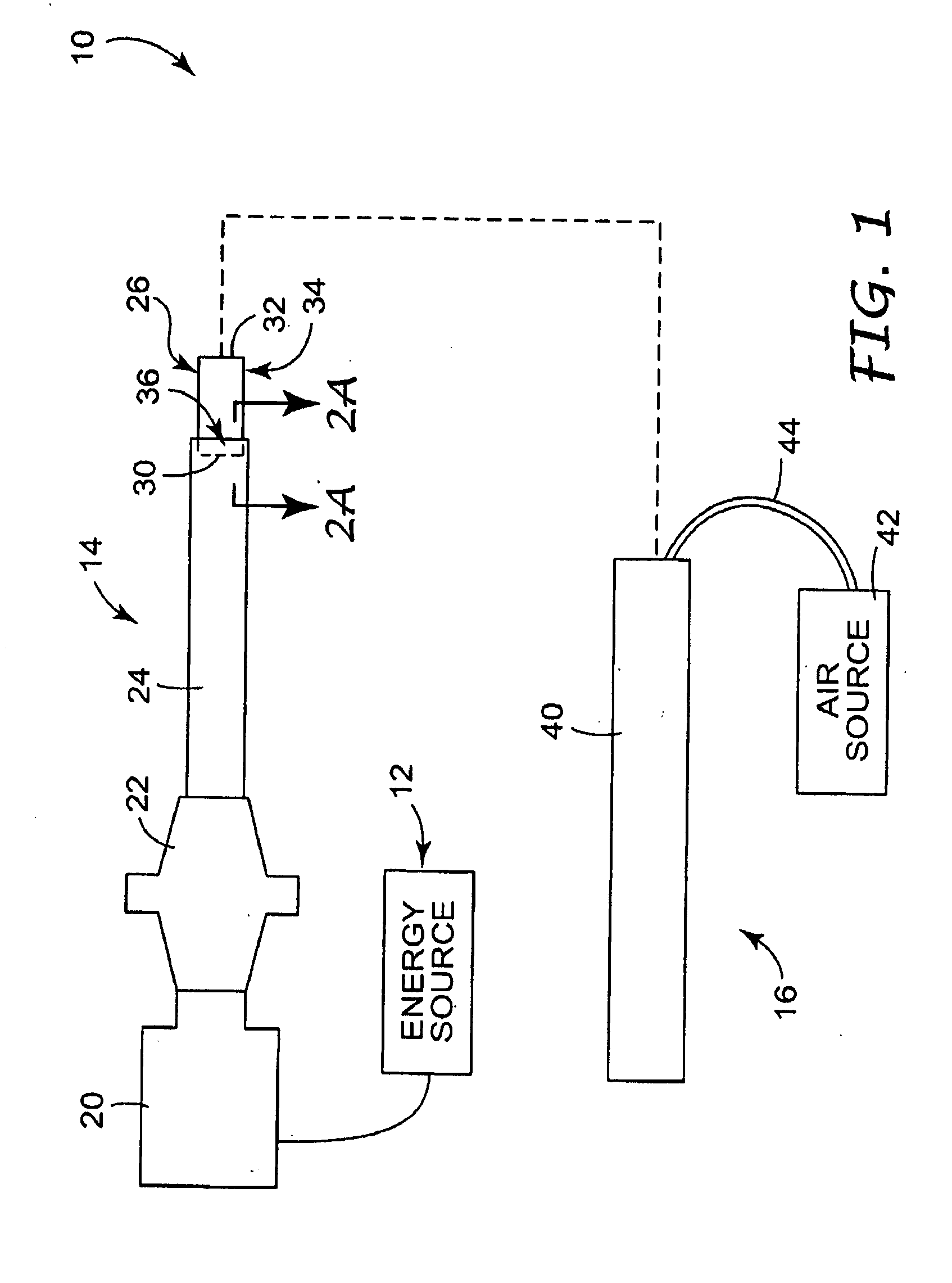
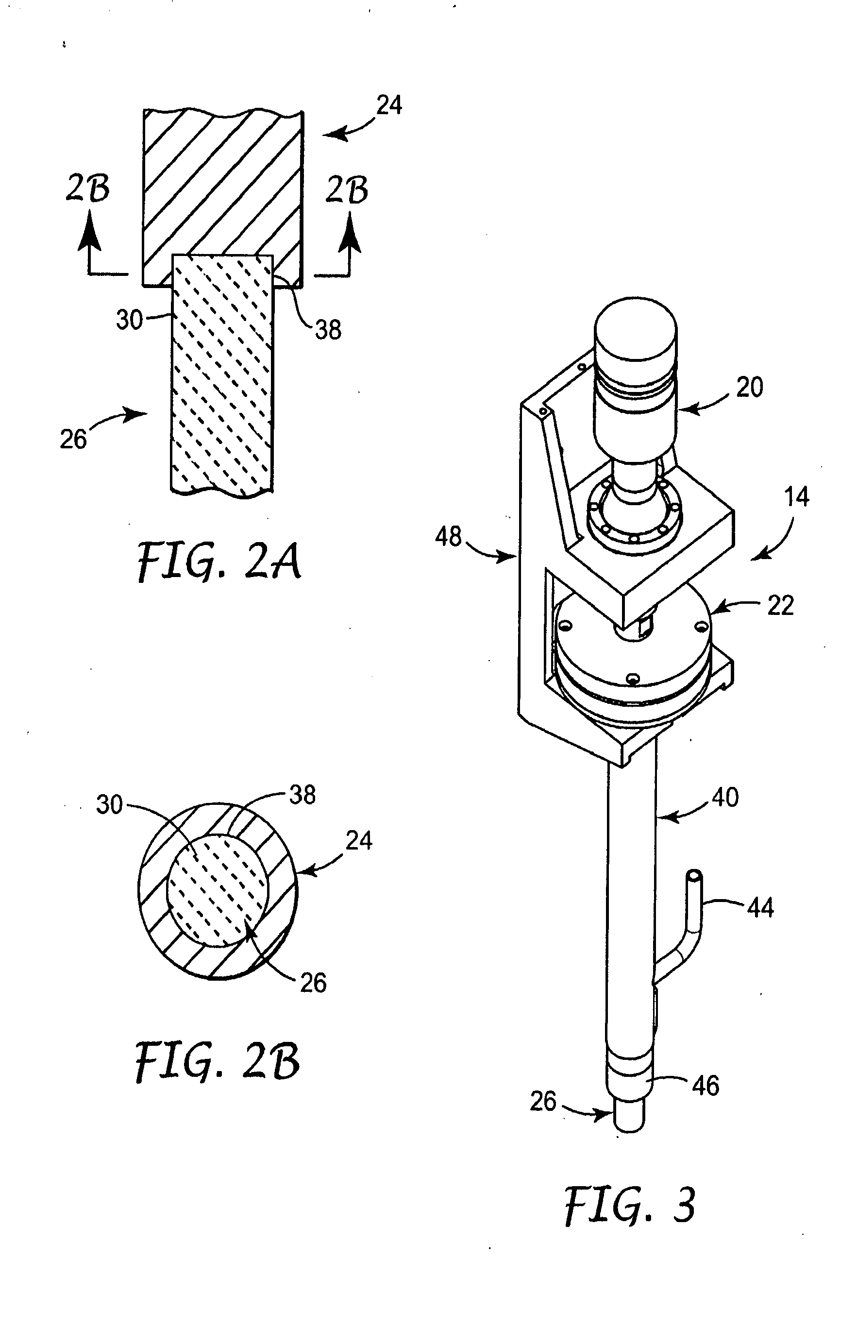
[0033] An ultrasonic horn stack was prepared by forming a cylindrical rod sialon horn having a length of approximately 11.75 inches and a diameter of 1 inch. The horn was interference fit-mounted to a titanium waveguide. The waveguide was mounted to a booster that in turn was mounted to a transducer. An appropriate energy source was electrically connected to the transducer. The so-constructed ultrasonic system was then operated to apply ultrasonic energy to a molten aluminum bath. In particular, aluminum metal was heated to a temperature in the range of about 705° C.-715° C. to form the molten aluminum bath. The ceramic horn was partially immersed in the molten aluminum bath, and the horn stack operated such that the horn transmitted approximately 65 watts at approximately 20 kHz and subjected to air cooling. At approximately 50-hour intervals, the horn was removed from the molten aluminum bath, acid etched, and visually checked for erosion. Further, stability of the junction betwee...

example 2

Preparation of Metal Matrix Composite Wires

[0034] Composite metal matrix wires were prepared using tows of NEXTEL™ 610 alumina ceramic fibers (commercially available from 3M Company, St. Paul, Minn.) immersed in a molten aluminum-based bath and subjected to ultrasonic energy to effectuate infiltration of the tow. In particular, an ultrasonic system that included a sialon horn, similar to the horn described in Example 1, was employed as part of a cast through methodology, shown schematically in FIG. 5. The process parameters were similar to those employed for fabricating aluminum matrix composites (AMC) and fully described in Example 1 of U.S. Pat. No. 6,344,270 ('270), herein incorporated by reference. The sialon horn of present invention replaced the niobium alloy horn described in the '270 patent. With this Example, the sialon horn transmitted about 65 watts at a frequency of about 20 kHz. Approximately 6,500 feet of wire was produced over the course of thirteen experimental runs...


PUM

PropertyMeasurementUnit
frequencyaaaaaaaaaa
temperatureaaaaaaaaaa

Abstract

An acoustic system for applying vibratory energy including a horn connected to an ultrasonic energy source. The horn defines an overall length and wavelength, and at least a leading section thereof is comprised of a ceramic material. The leading section has a length of at least ⅛ the horn wavelength. In one preferred embodiment, an entirety of the horn is a ceramic material, and is mounted to a separate component, such as a waveguide, via an interference fit. Regardless, by utilizing a ceramic material for at least a significant portion of the horn, the ultrasonic system of the present invention facilitates long-term operation in extreme environments such as high temperature and / or corrosive fluid mediums. The present invention is useful for fabrication of metal matrix composite wires.

Description

CROSS REFERENCE TO RELATED APPLICATION [0001] This application is a continuation of application Ser. No. 10 / 403,643, filed Mar. 31, 2003, which application is incorporated herein by reference.BACKGROUND OF THE INVENTION [0002] The present invention relates to acoustics. More particularly, it relates to an ultrasonic system and method incorporating a ceramic horn for long-term delivery of ultrasonic energy in harsh environments, such as high temperature and / or corrosive environments. [0003] Ultrasonic is the science of the effects of sound vibrations beyond the limit of audible frequencies. The object of high-powered ultrasonic applications is to bring about some physical change in the material being treated. This process requires the flow of vibratory energy per unit of area or volume. Depending upon the application, the resulting power density may range from less than a watt to thousands of watts per square centimeter. In this regard, ultrasonics is used in a wide variety of applic...

Claims


Application Information

Patent Timeline
Patent Type & Authority Applications(United States)
IPC IPC(8): H03H9/00B06B3/00B21C1/00B21C37/04B22D19/14C22C47/08H04R17/00
CPCB06B3/00B21C1/006B21C37/042B22D19/14B22F2999/00H04R17/00C22C47/08B22F2202/01B01J19/10B06B1/06H04R19/00
Inventor NAYAR, SATINDER K.GERDES, RONALD W.CARPENTER, MICHAEL W.AMIN, KAMAL E.
Owner 3M INNOVATIVE PROPERTIES CO
Why Eureka
Try Eureka